1-3
1
Read This First
Part Names
1-2 Part Names
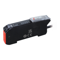
1-2-1 Sensor Amplifier
S
R
2
1
R
S
Cable length: 2 m, ø4.0
M8 4-pin plug
connector
Cable models
Connector (Only on main unit
and expansion units)
Fiber
insertion
holes
Connector
models
Lock lever
Setting keys
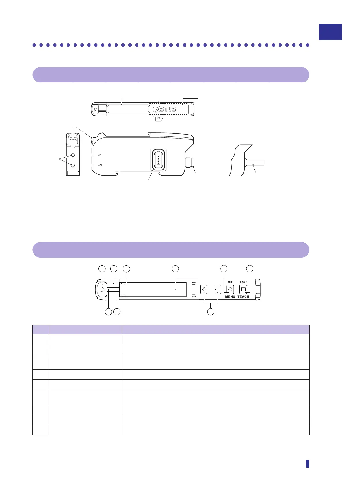
1-2-2 Display and Operation Section
S
R
1
2
743
No. Name Description
①
Lock lever Locks and releases the fiber unit.
②
Output 1 indicator (orange) Illuminates in orange when output 1 is ON.
③
Power indicator (green) Illuminates in green when the power is turned on, and blinks during IO-Link
communication.
④
Output 2 indicator (orange) Illuminates in orange when output 2 is ON.
⑤
Fiber insertion indicator Indicates the insertion status of the fiber unit.
⑥
OLED display Displays the present value and threshold of the received light amount and the
parameters during setting.
⑦
Selection keys (+/- keys) Manually adjusts the threshold, and select menu during setting.
⑧
OK/MENU key Selects a setting menu and sets the parameters.
⑨
ESC/TEACH key Performs teach and exits menus during setting.