2-8
Wiring the Fiber Amplier
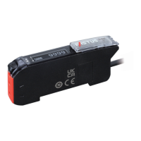
2-Output and 1-Input Models
z NPN setting
Brown
*1
Black
Gray
White
Blue
*1
12 to 30 VDC (stand-alone unit)
12 to 24 VDC
(inter-connection main unit)
Control output 1
Control output 2
External input
0 V
Load
Load
*1: Power supply wires (Brown, Blue) are not equipped on the inter-connection expansion units.
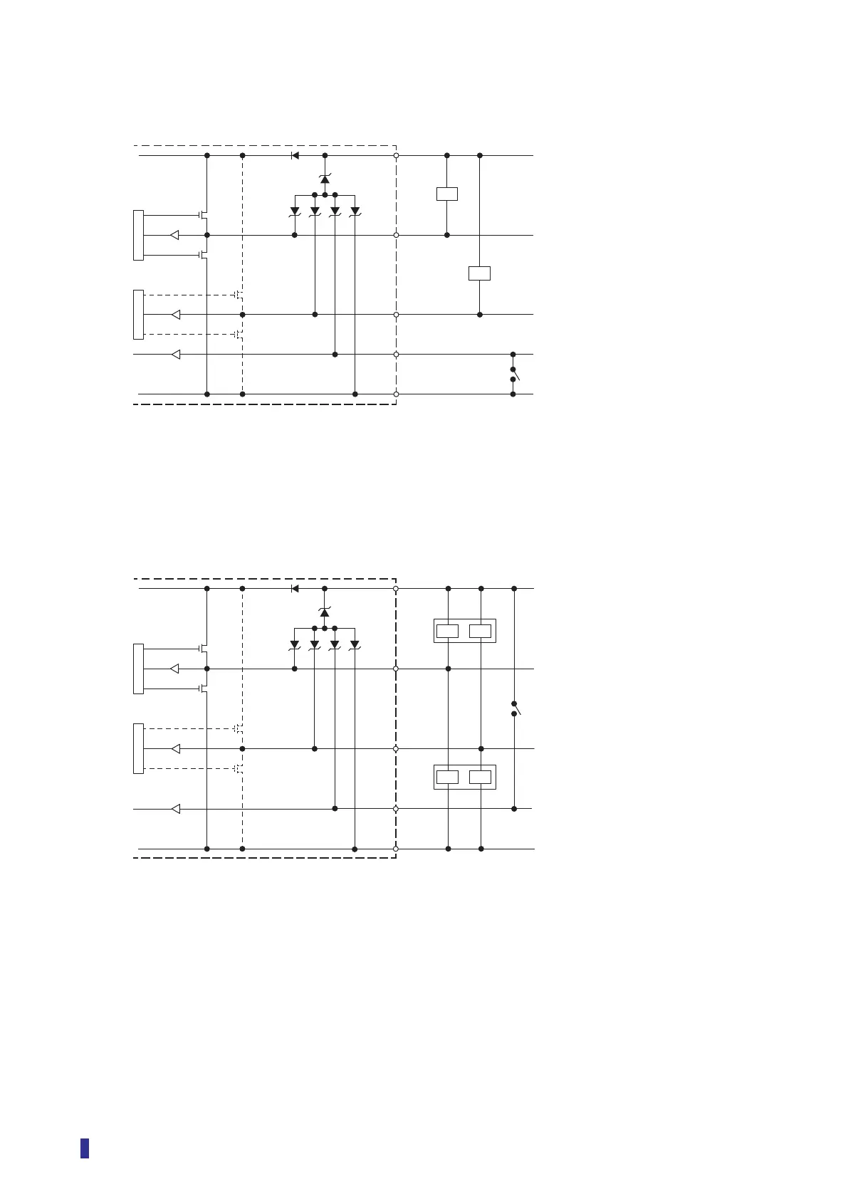
z PNP or Push-pull setting
Brown
*1
Black
Gray
White
Blue
*1
12 to 30 VDC (stand-alone unit)
12 to 24 VDC
(inter-connection main unit)
Control output 1
Control output 2
External input
0 V
*2
*3
Load
Load
Load
Load
*1: Power supply wires (Brown, Blue) are not equipped on the inter-connection expansion units.
*2: When I/O polarity is set to Push-pull and the sensor is connected with plus common circuits.
*3: When I/O polarity is set to Push-pull or PNP and the sensor is connected with minus common circuits.