164
CARE AND MAINTENANCE
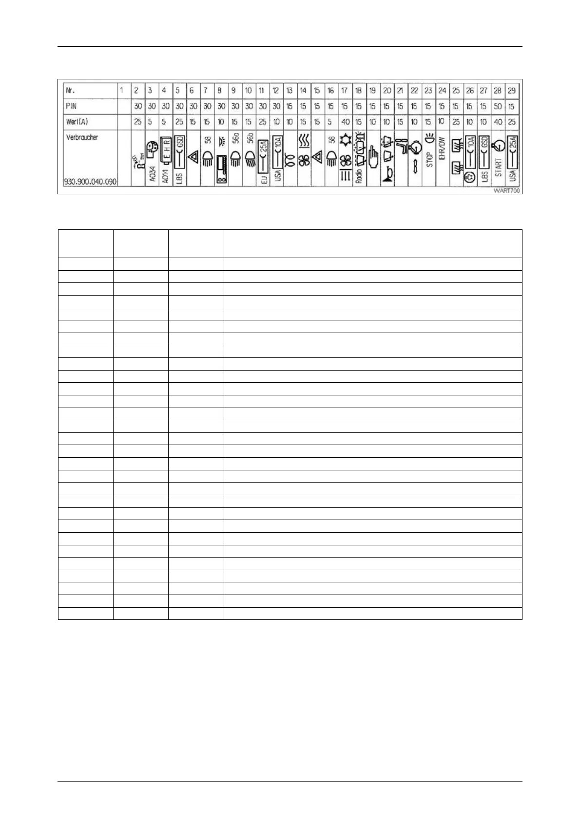
21.1 Fuse holder X050
Operation_Pic_number:1
Text-module
Fuse no. PIN Amps
(A)
Consumers
1-- -
2 30 25 Glow and starter switch in ON position
3 30 5 Joystick
4 30 5 Relay EPC Ub
5 30 25 LBS implement socket CAN bus connection
6 30 15 Hazard warning light pushbutton
7 30 15 Driving lamps pushbutton
8 30 10 Radio, cab interior lighting
9 30 15 Relay no. 56a (high beam)
10 30 15 Relay no. 56b (low beam)
11 30 25 Socket 25 A
12 30 10 10 A socket
13 15 10 Flame starting system
14 15 15 Heater switch
15 15 15 Hazard warning light pushbutton
16 15 5 Driving lamps pushbutton
17 15 40 Blower switch
18 15 15 Front screen wipers controller
19 15 10 Starter lockout switch, emergency operation relay
20 15 10 Steering column switch (combination switch)
21 15 15 Driver seat, heated seat
22 15 10 Engine brake
23 15 15 Brake relay
24 15 10 Hydraulic circuit 3
25 15 25 Rear window heater, mirror heater
26 15 10 Socket 10 A, reverse travel warning beep
27 15 10 LBS implement socket
28 50 40 Flame starting device in Start position
29 15 25 Not allocated
Fig.71
 Loading...