82
OPERATION
Operation_Pic_number:1
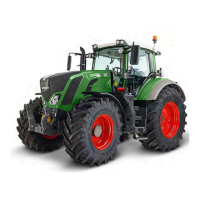
● Turn on slip control with key (F1).
A = Control sensitivity
B1 = Wheel slip setpoint
Setting range 3% - 60%.
B2 = Wheel slip actual value
Indication range 0% - 60%.
Text-module
Setting control sensitivity
● Keep limiting wheel slip with rotary control
(P2) until the desired working depth can just
be kept.
Text-module
If an uneven ploughing pattern is formed through
too frequent operation of the slip control:
● With the rotary switch (P1), set the control
sensitivity.
NOTE:
If the tractor stands still more than 30 se-
conds, slip control deactivates automatically.
Text-module
Adjusting the radar sensor
● Measure out and mark an exact distance bet-
ween 30 m and 100 m on the ground
(e.g. 100 m).
● Move the tractor to position the front wheel
exactly at the start mark.
Operation_Pic_number:1
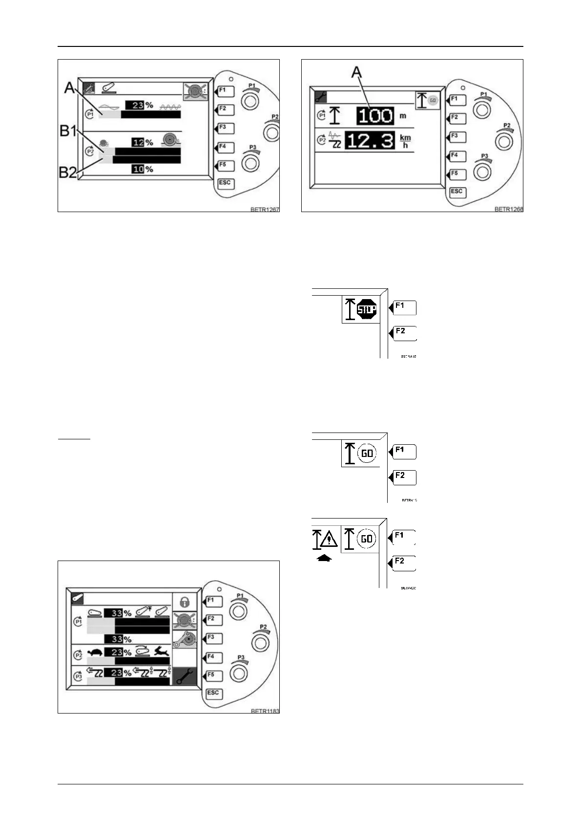
● Press key (F5). The following sub-menu ap-
pears.
Fig.174
Fig.175
Operation_Pic_number:1
● With rotary control (P1) set on display (A) the
measured distance on the ground
(e. g. 100 m).
● Press key (F1).
● Start the tractor off, and stop with the front
wheels at the end mark of the measured di-
stance.
● Press key (F1).
● Check whether the input distance corre-
sponds to the distance marked on the ground.
● Repeat calibration again.
Display changes from
'GO' to 'STOP'.
If completed
successfully, display
shows 'GO' again.
If the warning symbol
(arrowed) also
appears, the
adjustment process
must be repeated.
Fig.176
 Loading...