86
OPERATION
Releasing the side lock.
cat. II. = Put peg into hole (A).
cat. III. = Put peg into hole (B).
Fine adjustments of the lateral stabilisers are ob-
tained by screwing the threaded bolts in or out
(C).
Text-module
Checking:
● Before raising the hitched implement, it must
be possible to lock both lateral supports free
of play.
IMPORTANT:
Lower links automatically become rigid late-
rally, when the lifting arm is raised. Too tight
a setting will result in clamping in the three-
point linkage.
Height-adjustable lower links
Operation_Pic_number:1
● Insert bolt in lower hole (A).
Required for implements with outrigger wheels
and without swing compensation, e.g. for plan-
ting machines.
Lower link hook locking
Operation_Pic_number:1
Under particularly heavy operating conditions,
secure the lower link hooks against unintentional
release (e.g. for logging work).
● Insert bolts (e.g. M 8x50) in the holes (arro-
wed) and secure with nuts.
Fig.188
Fig.189
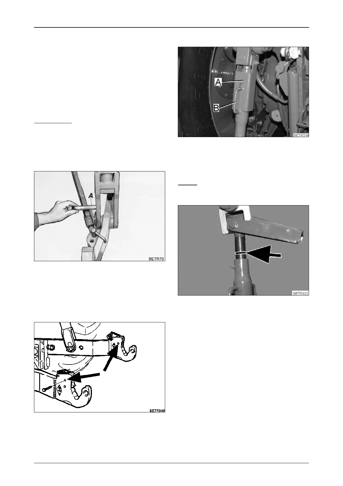
19.2 Extendable lifting struts
Operation_Pic_number:1
The lifting struts are extendable.
● Fold up the securing clamp (A).
● Adjust the lifting struts by turning handle (B).
NOTE:
It must still be possible for the securing
clamp (A) to be folded over button (B).
Operation_Pic_number:1
Maximum length is reached when the mark
(arrowed) is visible.
Fig.190
Fig.191
 Loading...