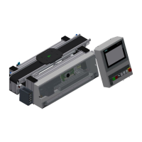
Design and function
© Festo Didactic Conveyor 59
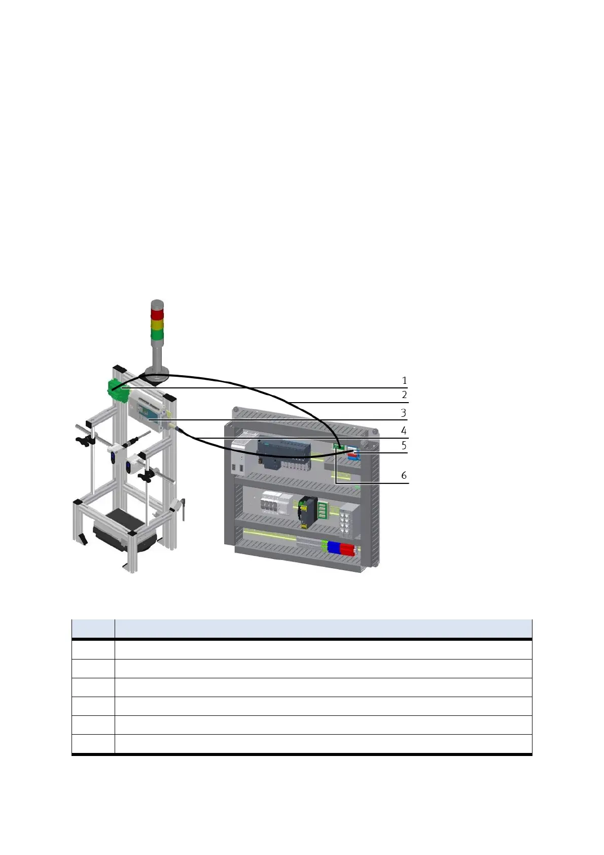
5.5.2 Connecting the CP application module electrically to the basic module CP Factory
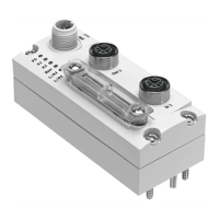
SysLink-interface for digital signals
The CP application module exchanges digital input and output signals with the basic module via the
SysLink interface:
Connect the I/O terminal (3) of the CP application module with the I/O terminal (5) on the electric board
of the basic module CP Factory. Therefore use the provided connecting cable with SysLink plugs (4).
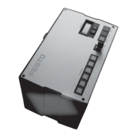
D-Sub-interface for analogue signals
The CP application module produces two analogue output signals with the distance sensors. These are set
on the analogue terminal (1) and have to be connected with the analogue inputs of the basic module:
Connect the analogue terminal (1) of the CP application module with the analogue terminal (6) on the
electric board of the basic module CP Factory. Therefore use the provided connecting cable (2) with
standard D-Sub plugs: 15-pin, two-rowed.
Electrical connections
CP application module: analogue terminal (+BG-XD2A)
connecting cable with 15-pin D-Sub-plugs
CP application module: I/O terminal (+BG-XD1)
connecting cable with SysLink-plugs (SysLink-cable)
electric board basic module CP Factory: I/O terminal (+K1-XD15)
electric board basic module CP Factory: analogue terminal (+K1-XD16A)