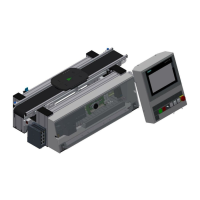
Design and function
© Festo Didactic Conveyor 39
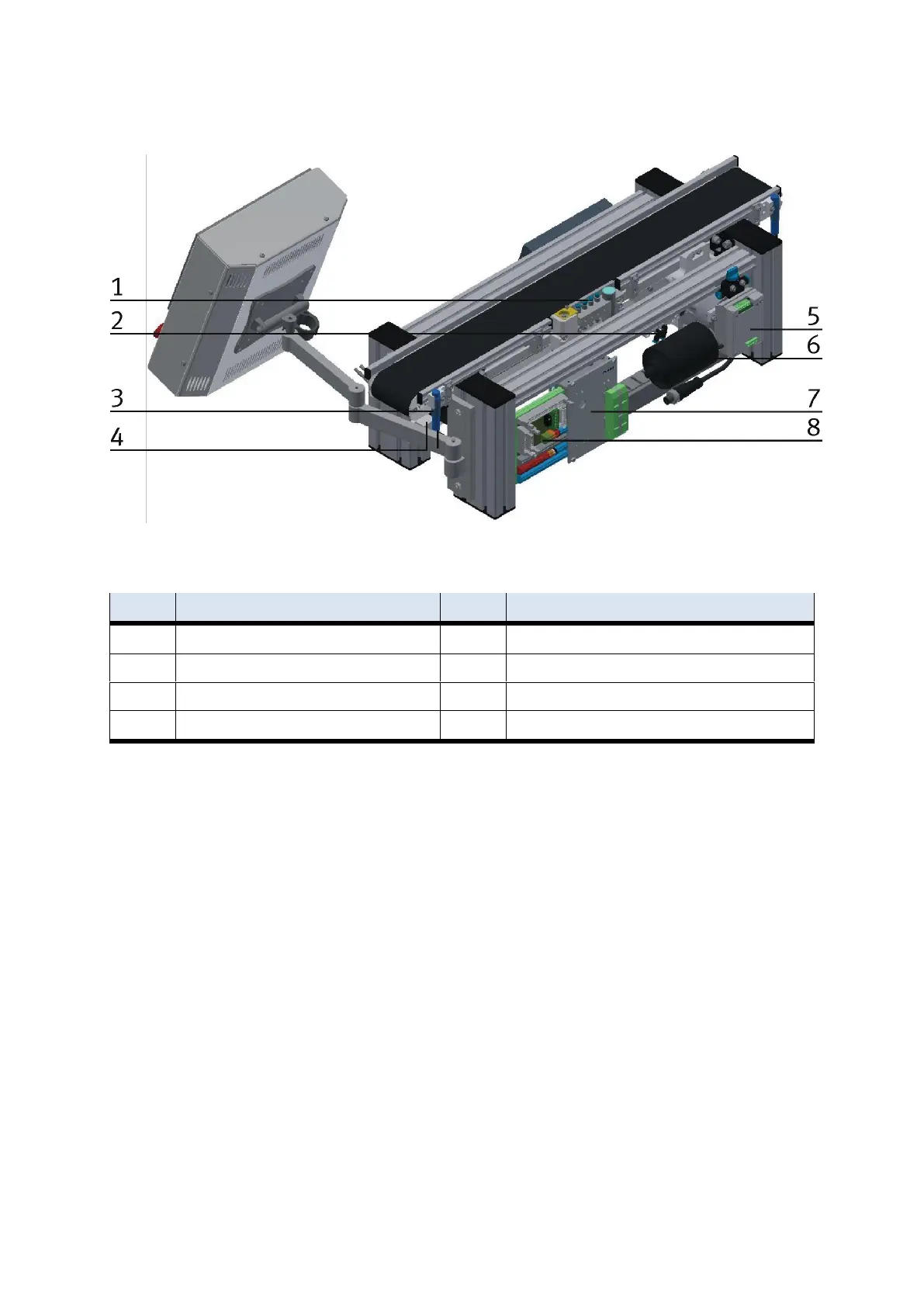
CP Lab conveyor rear view
2-quadrant controller for motor
Valve with manual override for stopper unit
alternatively 36 V motor / 230 V Motor / 400 V Motor
Capacitive sensor end of conveyor
Coupling sensor following station
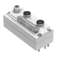
Circuit board backside XZ2
4.4 Stopper unit
The stopper unit is located in the middle of the CP Lab conveyor. The carrier runs over the extended stopper
unit. The screw (pos. 1 picture below) runs into the slot of the carrier. At the end of the slot the carrier is
stopped.
With the help of the sensors at the stopper unit, the carrier can be identified. There are two ways for
identifying:
Variant 1
It is identified by 4 inductive sensors; for this exercise, the carriers may be provided with grub screws at
different positions.
Variant 2
The identity is read by the RFID sensor.
It is also possible to use the first of the inductive sensors for controlling; in this case the first grub screw is
read and reports the position of the workpiece at the stopper.