Operation
© Festo Didactic Conveyor 87
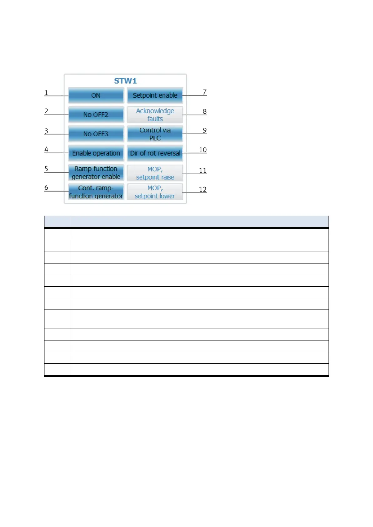
If the outputs are set, they are highlighted in blue. See training manual G120 page 124.
ON - Set the inverter to the "Ready to run" state, the direction of rotation must be set via Bit11.
No OFF2 - Coast to a standstill, immediate pulse inhibit, drive spins to a stop.
No OFF3 - Quick stop, fast stop: Shut down with the fastest possible deceleration rate.
Enable operation Control and inverter pulses are enabled.
Ramp-function generator enable
Enable HLG - enable ramp function generator
Enable setpoint - the value selected at the HLG input is enabled.
Acknowledge fault - A fault is acknowledged with a positive edge, and the inverter then switches to the "start-up inhibit"
state.
Guidance by PLC - Control via interface, process data valid
Direction reversal - motor will run counterclockwise in response to a positive setpoint.
MOP higher - set the motor potentiometer higher
MOP lower - Lower the motor potentiometer