Operation
© Festo Didactic Conveyor 89
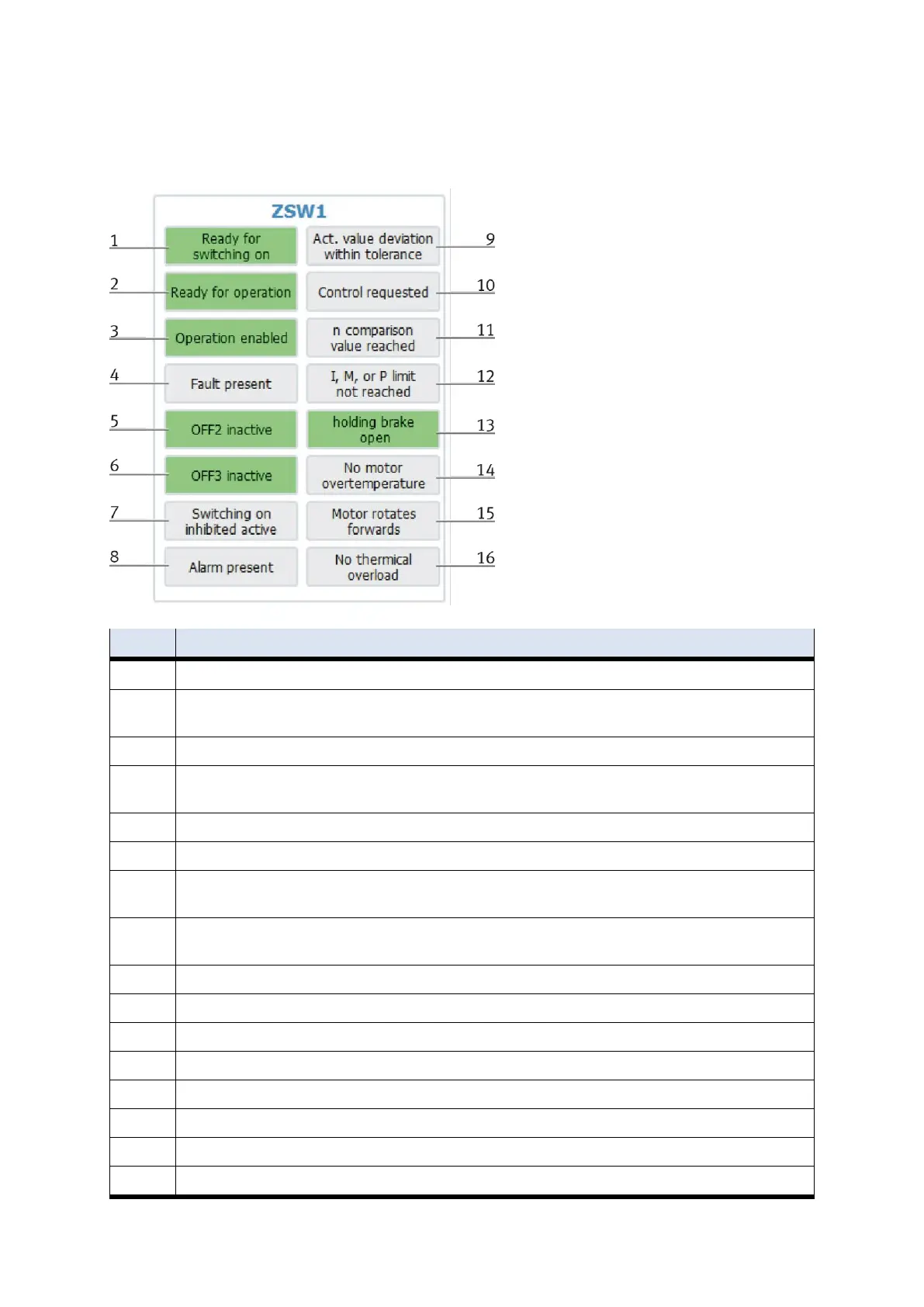
Display of inverter status, active displays are highlighted in green.
See training manual G120 - page 125.
Ready for switching on - power supply is switched on, electronics are initialized, pulses are blocked.
Ready for operation - Inverter is switched on (ON command is pending), no fault is active, inverter can start as soon as
the command "Enable operation" is given. See control word 1, bit =
Operation enabled - drive follows setpoint. See control word 1, bit 3.
Fault present - drive faulty. There is a fault in the drive, which means that it is not in operation and switches to the
"startup inhibit" state after successful rectification and acknowledgment of the fault.
OFF2 inactive - "coast to standstill" command is pending.
OFF3 inactive - Quick stop command is active.
Switch-on disable active - The drive is only switched back to the "switched on" state if the commands "no coast down"
AND "no quick stop" - followed by "ON" - are given.
Alarm present - drive still in operation; Warning in service / maintenance parameter; no acknowledgment; see alarm
parameter r2110.
Act. value deviation within tolerance - setpoint-actual value deviation within the tolerance range.
Control requested - The automation system is requested to take over control.
N comparison value reached
I, M, or P-limit not reached
Holding brake open - signal can be used to control a holding brake