3. Installation
3-12
Festo P.BE-SPC11-SYS-ASI -EN en 0203NH
Measuring system ( 7 )
See also “Drive-specific supplement.”
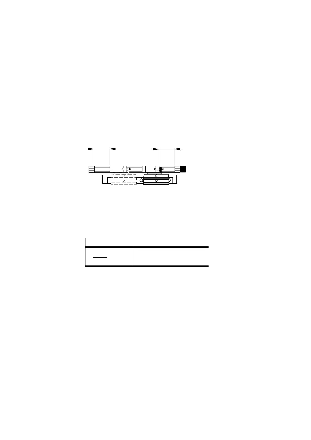
S Fit the measuring system and the drive symmetrically so
that the centre of the usable measuring system stroke
corresponds to the centre of the complete cylinder stroke.
With type MLO-POT-...-TLF:
The remaining path of the measuring system slide must be
identical in the cylinder end positions on both sides.
1 Remaining slide
path
11
Fig. 3/5: Symmetrically mounted measuring system (with type ML O-PO T-...-TLF)
With type MLO-POT-...-LWG:
The remaining slide path of the measuring system must be
identical in the cylinder end positions on both sides and can
be calculated as follows:
Calculation formula
Description
(
L
M
-L
Z
)
2
= L
R
L
M
Measuring system length
L
Z
Cylinder length
L
R
Remaining slide path

 Loading...