FLAMIC S.R.L. 5 Via dell’Artigianato, 36035 Marano Vicentino (Vicenza) - Italy
20
Dough sheeter SF450 - SF500 - SF600 Operation and maintenance manual (translation of original instructions) – Ed. 10/2016
Rev.02 10/2017
All rights reserved. Reproduction in whole or in part of this manual is prohibited.
2
3.4 INSTALLING/REMOVING THE TABLES OF A SHEETING MACHINE (MOD. SF600)
The instructions 3.4.1 for installing the tables of a model SF600 sheeting machine are given in section 3.2,
which, as explained in section , when supplied by Flamic, have to be installed on the machine (even if they are
received in the same package. See Figure 8/A).
Instructions 3.4.2 for their removal are given in section
Models SF450 and SF500 on the other hand, are supplied with the tables already installed. Their removal and
installation, which is only necessary for maintenance purposes (for example to replace the conveyor belts),
involves complex tasks which must be carried out by FLAMIC technicians, or anyway by very experienced
(special/extraordinary maintenance) mechanical technicians. The instructions are given in section 4.6.
The installation/removal of tables for model SF600 machines requires two operators at the same time to carry
out the work, of which at least one has mechanical installation experience. The second operator is required to
help support the table while the work is being carried out. Before starting, lock the wheels of the machine with
the brake levers (see Figure 10) and wear at least safety footwear with reinforced toecaps and abrasion
resistant work gloves.
To make the work easier, completely raise the interlocked guards in the roller infeed zone (see section 3.5.2).
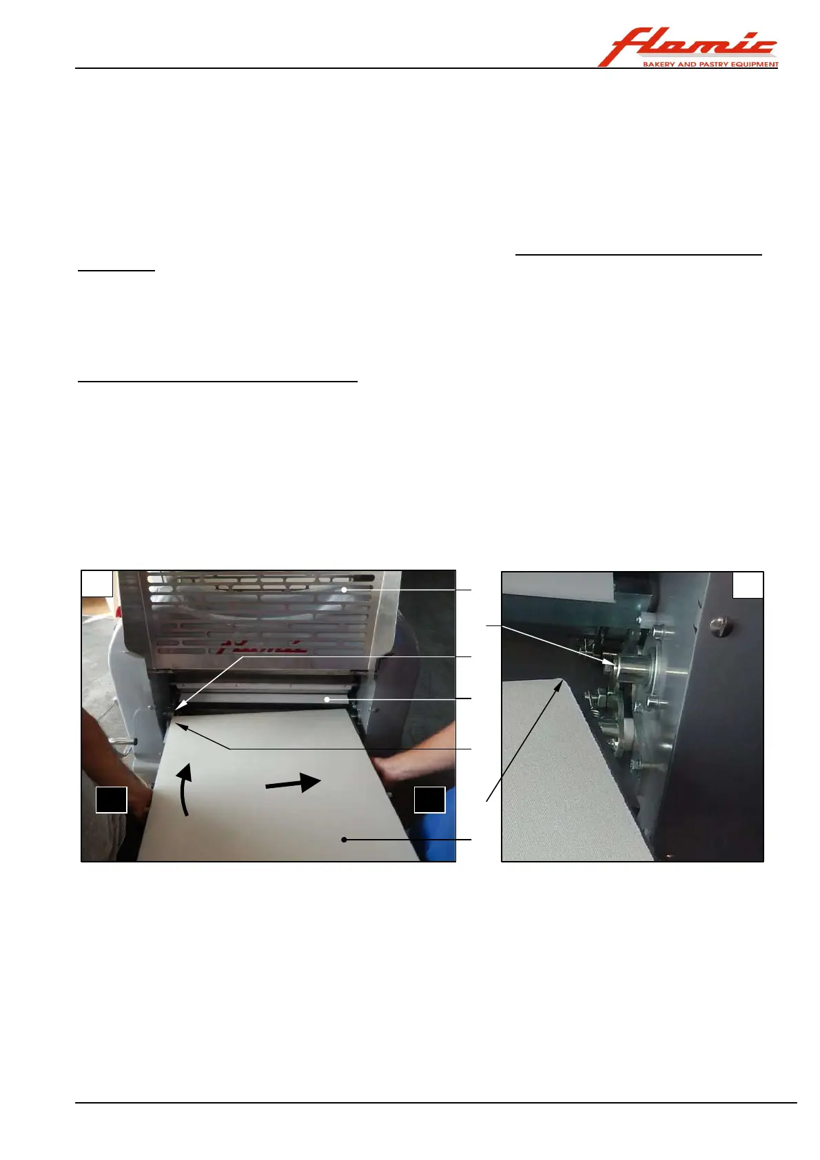
3.4.1 INSTALLING A TABLE (MOD. SF600)
Wear at least the PPE indicated in section 3.4. With reference to Figure 12, raise the guard ref. 6 completely
(see section 3.5.2) on the side on which the table is to be installed (photo A) and remove the scraper ref. 7
(section 4.5 and section 4.5.2.3).
The table must be kept in a horizontal position by holding it at points far enough apart so that it can be easily
supported. Whilst operator X supports his side of the table ref. 1, operator Y (experienced mechanic), whilst also
supporting the table, engages the end of the roller ref. 3
with the cylinder ref. 2 that protrudes from the upright. He must then push the bench in the direction indicated by
the arrow F1 in order to compress the spring (not visible in the figure) that pushes the cylinder ref. 2 outwards.
Immediately afterwards (almost at the same time) he must move the bench in the direction indicated by arrow
F2 so that the cylinder ref. 5 is inserted in the other end of the roller ref. 4. Rest the table in a horizontal position
on its support (section 3.6.3). Then install and fasten the scraper ref. 7 (see section 4.5 and section 4.5.2.3).
Figure 12 - Installing the benches (mod. SF600)
3
1
4
5
6
7