FLAMIC S.R.L. 5 Via dell’Artigianato, 36035 Marano Vicentino (Vicenza) - Italy
35
Dough sheeter SF450 - SF500 - SF600 Operation and maintenance manual (translation of original instructions) – Ed. 10/2016
Rev.02 10/2017
All rights reserved. Reproduction in whole or in part of this manual is prohibited.
4 MAINTENANCE
4.1 FOREWORD
Unless otherwise specified, all work covered in this section can be considered ordinary maintenance. Any other
type of maintenance however, is considered special/extraordinary maintenance (for definitions of ordinary and
special/extraordinary maintenance see section 1.4). In case of doubt, contact Flamic s.r.l.
WARNING!
All maintenance and cleaning should only be carried out after having:
- pressed the stop button ref. 3 Figure 4
- turned the main switch to O - OFF ref. 1 Figure 4.
- remove the power plug from the power outlet (the disconnected plug must remain clearly visible so that
anyone can check that power has been disconnected)
in order to prevent the machine or its part(s) being started and by other people.
- and (for version “V”) after having waited a sufficient amount of time for the residual voltages in the inverter to
have discharged (for further details see section 4.8 and section 5.2.4.7).
Whenever it is necessary to remove a guard or disable a safety device, take all the necessary
precautions to prevent other people being exposed to the consequent risks (for example, delimit the work
area with white-red chains and display work in progress warning signs). All guards should be replaced and
secured with all the fastenings provided and every safety device should be re-enabled as soon as there is
no longer any reason for it/them to be removed/disabled.
Anyone who fails to comply with these instructions and/or uses the machine improperly or inappropriately and
causes, directly or indirectly, injury to people, animals or damage to property will have to accept full
responsibility thereof.
4.2 MAINTENANCE AND PERIODIC CHECKS
Before starting, implement the safety measures set out in section 4.1.
• At the end of a shift or working day, thoroughly clean the machine (section 4.10)
• At the start of each working day or shift, check the working efficiency of the guards and safety devices
by carrying out the checks described in section 5.2.3.
4.3 DRIVE BELT TENSION ADJUSTMENT AND REPLACEMENT
Before starting, implement the safety measures set out in section 4.1 and wear work gloves.
These operations are considered extraordinary maintenance.
Check the tension of the drive belts frequently during the first 24-48 hours of operation (running in) and
afterwards, every two weeks. If you notice an uneven movement of the rollers and conveyor belts or you hear
any unusual noises or "fluttering" (a sign that the belts are slipping), check and adjust if necessary.
4.3.1 GENERAL RULES FOR CHECKING THE TENSION OF A DRIVE BELT
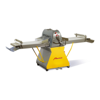
With reference to Figure 29, in general, to check the tension of a drive belt, proceed as follows:
a) Measure the length of the free section D [mm] between the pulleys P1 and P2
b) b) At the centre of and perpendicular to section D, apply the force T that is required to deflect the belt by a
value A (mm) use a millimetre scale to measure the deflection.
c) The tension of the drive belt is correct if the force T applied to obtain the deflection A corresponds to the
value that varies according to the type of belt and that is specified in the following paragraphs on a case by
case basis.
Use a dynamometer or tension meter to measure the force (the latter usually also allows you to obtain the
measurement of A), both of which are readily available commercially.
IMPORTANT! A drive belt that is too taught will wear quickly. On the other hand, if it is too slack it will
not work and will not transmit motion.
Figure 29 - Diagram showing the parameters used for tensioning a drive belt
P1
P2