FLAMIC S.R.L. 5 Via dell’Artigianato, 36035 Marano Vicentino (Vicenza) - Italy
51
Dough sheeter SF450 - SF500 - SF600 Operation and maintenance manual (translation of original instructions) – Ed. 10/2016
Rev.02 10/2017
All rights reserved. Reproduction in whole or in part of this manual is prohibited.
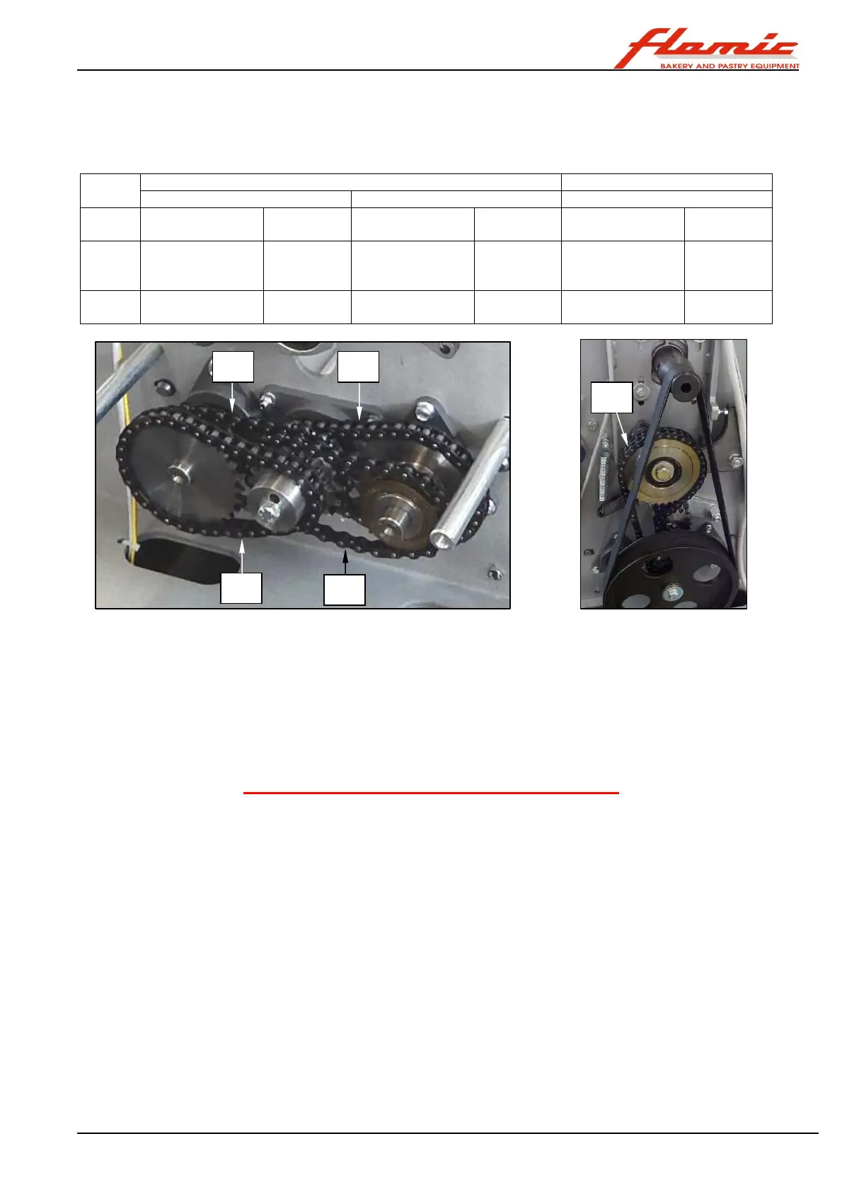
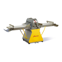
In the table below, with reference to Figure 43, the length (in number of pitches) and the part number for
ordering it from Flamic is indicated for each chain for each model of dough sheeter.
The chains are provided with all the accessories necessary for connecting their ends (joints, connecting links
etc.)
Controls side (single chain) Opposite side (double chain)
Mod. Type and No. of
pitches
Code Type and No. of
pitches
Code Type and No. of
pitches
Code
SF450
SF500
06-B1 3/8 x
7/32”
36 pitches
109010030
081-1 1/2 x 1/8”
27 pitches
109010031
06-B2 3/8 x
7/32”
69 pitches
109010027
SF600
083-1 1/2 x 3/16”
30 pitches
126010022
083-1 1/2 x 3/16”
28 pitches
126010023
06-B2 3/8 x
7/32” 73 pitches
126010025
Figure 43 - Drive chains
4.8 ELECTRICAL SYSTEM MAINTENANCE
Given the high risk and the severity of harm that may be caused in the event of an accident,
all work, even if
simple (e.g. replacing a fuse), that is related directly or indirectly to the electrical equipment of the machine
must be carried out by authorised experienced technicians (special/extraordinary maintenance) who
possess the technical and regulatory knowledge to carry them out safely and in a workmanlike manner.
They must first read and understand the contents of this manual.
The same applies for the replacement of the safety micro switches, described in detail in section 4.9.
Because of the nature of the checks and any adjustments that need to be carried out this work also requires
mechanical skills and knowledge.
WARNING FOR MACHINES FITTED WITH AN INVERTER
After having switched off and isolated the power supply, a residual voltage in the inverter could pose a
serious safety hazard for persons that come into contact with parts still powered by this voltage.
Section 5.2.4.7 provides further details on the subject and information regarding the precautions to take
to avoid exposure to hazards of an electrical nature.
4.9 REPLACING THE MICRO SWITCHES OF THE INTERLOCKED GUARDS
Bearing in mind what was written in section 4.8,
before starting, follow the procedure indicated in section 4.1.
With reference to Figure 44, to access the micro switches ref. 1 of the interlocked guards ref. 2
- mod. SF 450: remove the rolling thickness adjustment handle, the rack and the casing from the upright on the
controls side (photo A) by following the instructions in section 4.6.1 from point 1 to point 6.
- mod. SF500 and SF600: remove the casing from the side opposite the controls by following the instructions in
section4.3.3.
The micro switches ref. 1 of model SF 450 are shown in photo A and those of models SF 500 and SF600 in photo B
To replace a micro switch, proceed as follows:
1. using a hex wrench (Allen key), remove the screws ref. 3 (photo C)
2. using a cross-head screwdriver, remove the screw ref. 4 and then remove the cover to access the contacts ref. 5
(photo D)
3. loosen the screws ref. 6 of the terminals (photo E) and unscrew the cable gland ref. 7. Remove the cables ref. 8
from the micro switch, noting the position of the white and brown wires with respect to the terminals.
4. Insert the wires ref. 8 into the new micro switch and connect them to the terminals according to the positions
noted above. Tighten the screws ref. 6 and then tighten the cable gland ref. 7.
5. Replace the cover ref. 5 and fasten it using the screws ref. 4.
C1
C1
C2
C2
C3