FLAMIC S.R.L. 5 Via dell’Artigianato, 36035 Marano Vicentino (Vicenza) - Italy
50
Dough sheeter SF450 - SF500 - SF600 Operation and maintenance manual (translation of original instructions) – Ed. 10/2016
Rev.02 10/2017
All rights reserved. Reproduction in whole or in part of this manual is prohibited.
4.6.2 SHEETER MOD. SF600
The instructions for installing and removing a table are given in section 3.4. Once the table has been removed,
the procedure for replacing the conveyor belt is the same as described for models SF450 and SF500 in section
4.6.1, from point 17 to point 21.
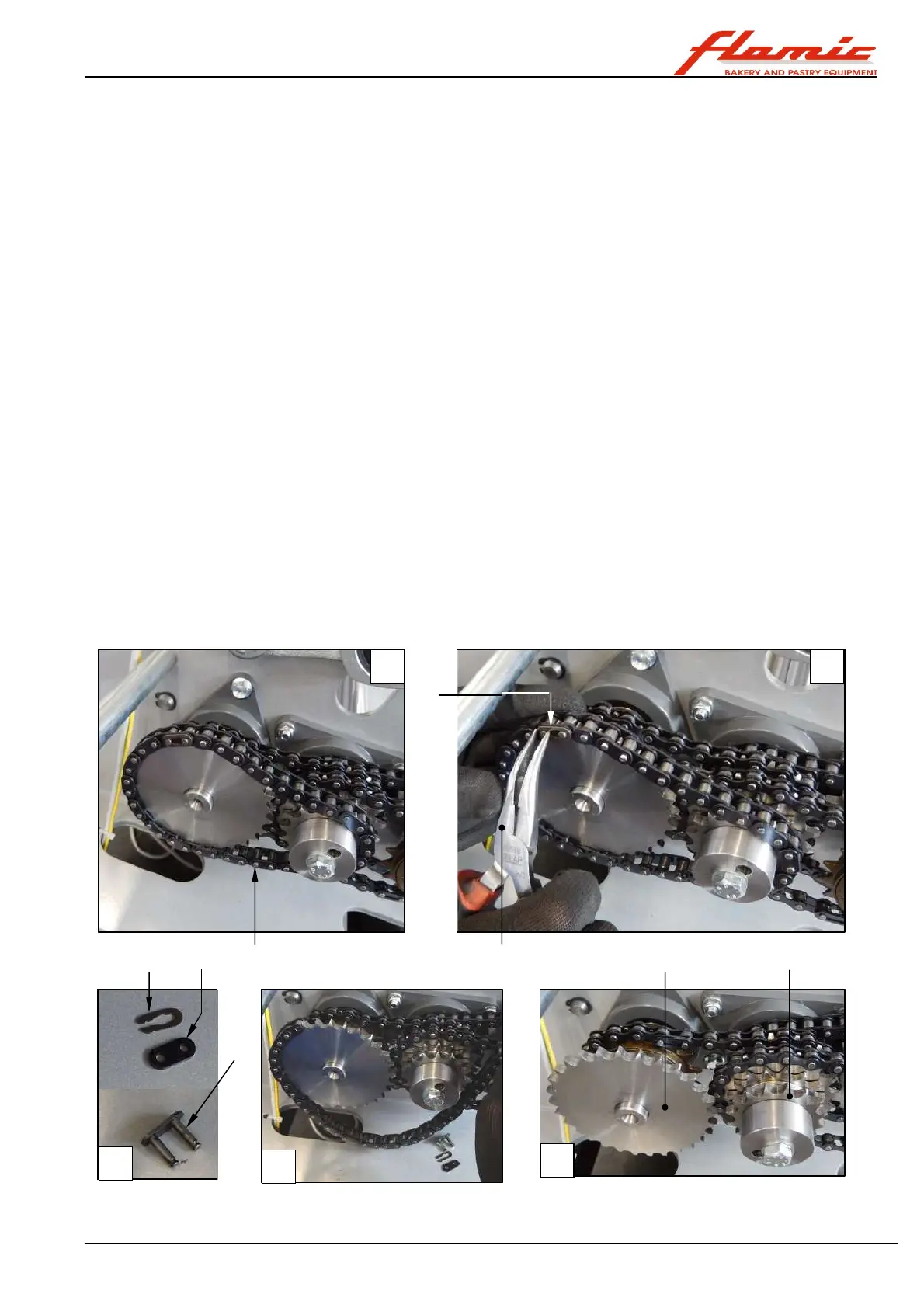
4.7 REPLACING A DRIVE CHAIN
Before starting, implement the safety measures set out in section 4.1 and wear work gloves.
This operation is considered special/extraordinary maintenance.
With reference to Figure 42, to remove, for example, the chain ref. 1:
1. Remove the casing of the side on which the chain is to be replaced; for the controls side casing, follow the
instructions in section 4.6.1 from point 1 to point 6 (these are also valid for model SF600). For the casing on
the opposite side, follow the instructions in section 4.3.2 for model SF450 or section 4.3.3 for models SF500
and SF600
2. Using a pair of needle nosed pliers ref. 2, remove the joint ref. 3 (photo B). Then remove the link plate ref. 4
and remove the pair of pins ref. 5 (photo C). The chain ref. 1 can now be removed (photos D - E)
To install a new chain:
3. Wrap it around the gears (ref. 6 and ref. 7 in the example shown in Figure 42). Then join its ends so that after
you have positioned the plate ref. 4, you can insert the pair of pins ref. 5 in the holes of the external link plate
(use new plates and pins. The joint ref. 3 should also be new).
4. Lastly, fasten the link with the spring clip ref. 3 using the long-nose pliers ref. 2.
5. Once finished, replace the casing that had been previously removed and secure it using all the screws and in
the manner indicated.
The chain is properly tensioned when it does not appear to be rigid (otherwise there is the risk of it breaking)
when pressed in the middle of a free section with your thumb, but it gives a little and then springs back to its
original position. The links of the chain should be just free enough to rotate on the pins, but at the same time not
slack (otherwise they could slip off the gear). If you are unsure about how to correctly adjust the tension of the
chain, do not use the machine and contact Flamic as soon as possible who will provide you with the necessary
information. The tension of the chain should be checked, as described above, at least every two weeks.
Figure 42 - Replacing a drive chain
1
3
3 4
5
2 6 7
A B
C
D
E