FLAMIC S.R.L. 5 Via dell’Artigianato, 36035 Marano Vicentino (Vicenza) - Italy
49
Dough sheeter SF450 - SF500 - SF600 Operation and maintenance manual (translation of original instructions) – Ed. 10/2016
Rev.02 10/2017
All rights reserved. Reproduction in whole or in part of this manual is prohibited.
48
49
50
47
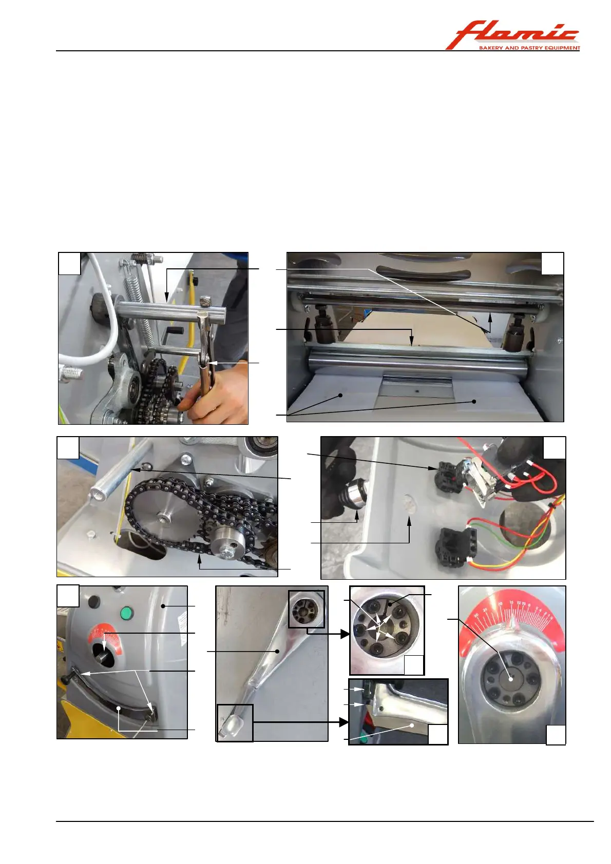
40. install the rack ref. 7 and secure it using the two screws ref. 8 (photo H)
41. replace the screws ref. 2 of the handle ref. 6 locking assembly ref. 4 into their original position. Place the
handle ref. 6 on the shaft ref. 5 (photo I) and position it 2-3 mm from the rack ref. 7 (the pin ref. 7 protrudes a
few mm with respect to the locking assembly). Then gradually tighten the screws ref. 2 in a crosswise pattern
(see tightening sequence example V1 to V5 in photo K). Stop when the screws start to become tight.
42. keep the plate ref. 54 under the hand grip of the handle ref. 6 pressed so that the tooth ref. 55 is disengaged
from the rack. Then move the handle through the length of its stroke and check (also by using a thickness
sample) that the distance between the tooth ref. 55 and lower profile of the plate ref. 7 is 2-3 mm in every
position (photo J) and that in every position between handle and the internal face of the rack there is a gap of
approximately 2 mm.
43. check that the sheets of paper ref. 47 are pressed between the rollers (it must not be possible to remove
them by pulling)
44. check that the tooth ref. 55 engages properly at several points of the plate ref. 7
45. engage the handle in the fourth notch of the rack starting from the lowest rolling thickness and using a torque
wrench set to 7 Nm (no greater in order not to damage the locking assembly), gradually tighten the screws
ref . 2 in a crosswise pattern (see tightening sequence example V1 to V5 in photo K).
46. insert the boss ref. 1 Figure 37/A in its seat on the locking assembly
Figure 41 - SF450 and SF500: installing the handle and other parts
47. Install the casing on the side opposite the controls (see section 4.3)
48. Install the lower scraper and, if appropriate, the upper scraper unit (see section 4.5)
49. adjust the tension of the conveyor belt (see section 4.4)
50. insert and (for SF500) secure the residue collection tray in position (see section 3.8).
11
46
51
53
52
9
8
7
4
5
2
6
5
54
55
7
D
F
E
G
H
V1
V2
V3
V4
V5
End