FLAMIC S.R.L. 5 Via dell’Artigianato, 36035 Marano Vicentino (Vicenza) - Italy
28
Dough sheeter SF450 - SF500 - SF600 Operation and maintenance manual (translation of original instructions) – Ed. 10/2016
Rev.02 10/2017
All rights reserved. Reproduction in whole or in part of this manual is prohibited.
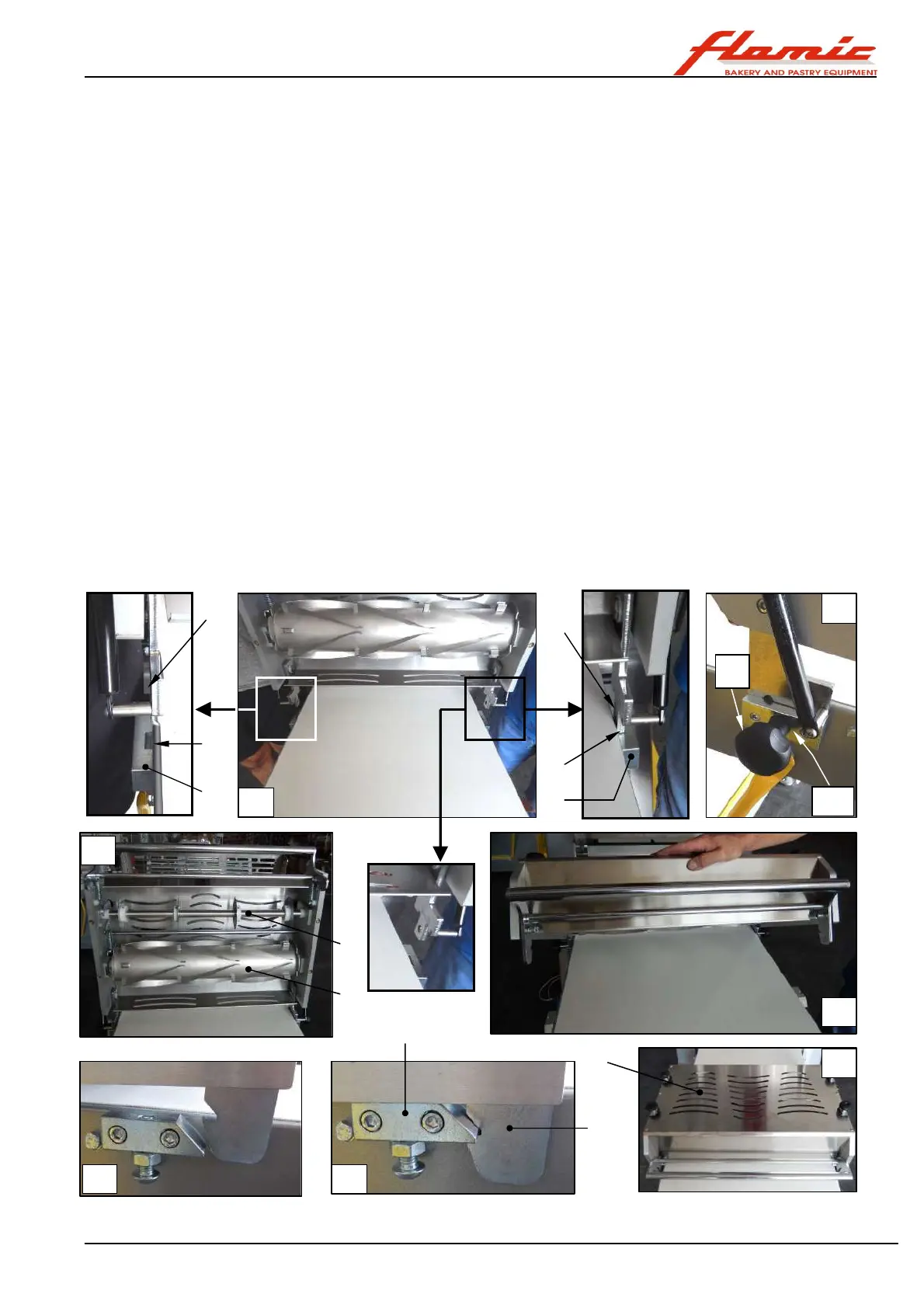
3.10 CUTTING UNIT (only for SF600V with bench lengths of 1400 mm or greater)
With reference to Figure 22, both sides of the benches designed to be used with the cutting unit ref. 1 are fitted
with the following devices (photo A - B):
- blocks ref. 7 with threaded knob ref. 2, in which to insert the side plates of the cutting unit,
- positioning plates ref.9 for engaging and holding the cutting unit against the table.
3.10.1 INSTALLING AND POSITIONING THE CUTTING UNIT
This must be carried out with the machine switched off and with the main power switch in the O - OFF position.
With reference to Figure 22, to install the cutting unit ref. 1 proceed as follows:
- wear safety footwear with reinforced toecaps and abrasion resistant gloves
- unscrew and completely remove the knobs with threaded studs ref. 2
- even if the weight is not particularly high (max. 23 kg), the following must be carried out by two people in order to
minimize the risk of musculoskeletal injuries and ergonomic injuries in general. In order to reduce the weight to be
lifted as much as possible, remove the cutting rollers ref. 3 and ref. 4 (the weight is reduced to approximately 15 kg).
This is particularly important where it is not possible to have the assistance of a second person. Raise the unit ref. 1
and place it like a bridge over the bench as shown in photos A - C. Then insert the plates ref. 5 into the seats ref. 6 in
the blocks ref. 7 at the sides of the bench and lower the unit under its own weight as far as it will go (photo C).
- after having placed the studs of the knobs into the through hole ref. 10 in the blocks ref. 7, screw the knobs ref. 2 as far
as they will go into the lateral threaded holes of the plates ref. 5 (photo B), but without tightening them excessively.
- when reinstalling the rollers, remember that the cutting roller ref. 3 must be positioned on the side from which
the dough arrives, i.e. usually on the side of the thicknessing rollers (for removing and installing the cutting
rollers see section. 3.10.4.
- lower the unit onto the bench, guiding it by hand (photo D). When it stops (photo E), push it firmly downwards until you
hear a loud metallic click. This indicates that the hook ref. 8 has engaged with the positioning plate ref. 9 (photo F) and
that the unit is secured to the bench, as shown in photo G (make sure that it has been properly engaged on both sides).
In this configuration, the maximum thickness of the dough that can pass under the cutting unit is 7 mm.
Figure 22 - Installing the cutting unit
1
3
4
5
5
6
6
7
7
8
9
2