When all the work is complete, cancel the safety measures in the reverse sequence.
2.3 General information
Introduction
All work on the gear unit should be performed with care and only by qualified personnel.
Symbols on the gear unit
The following symbols apply to the gear unit; some of which are found as coloured markings
on the gear unit:
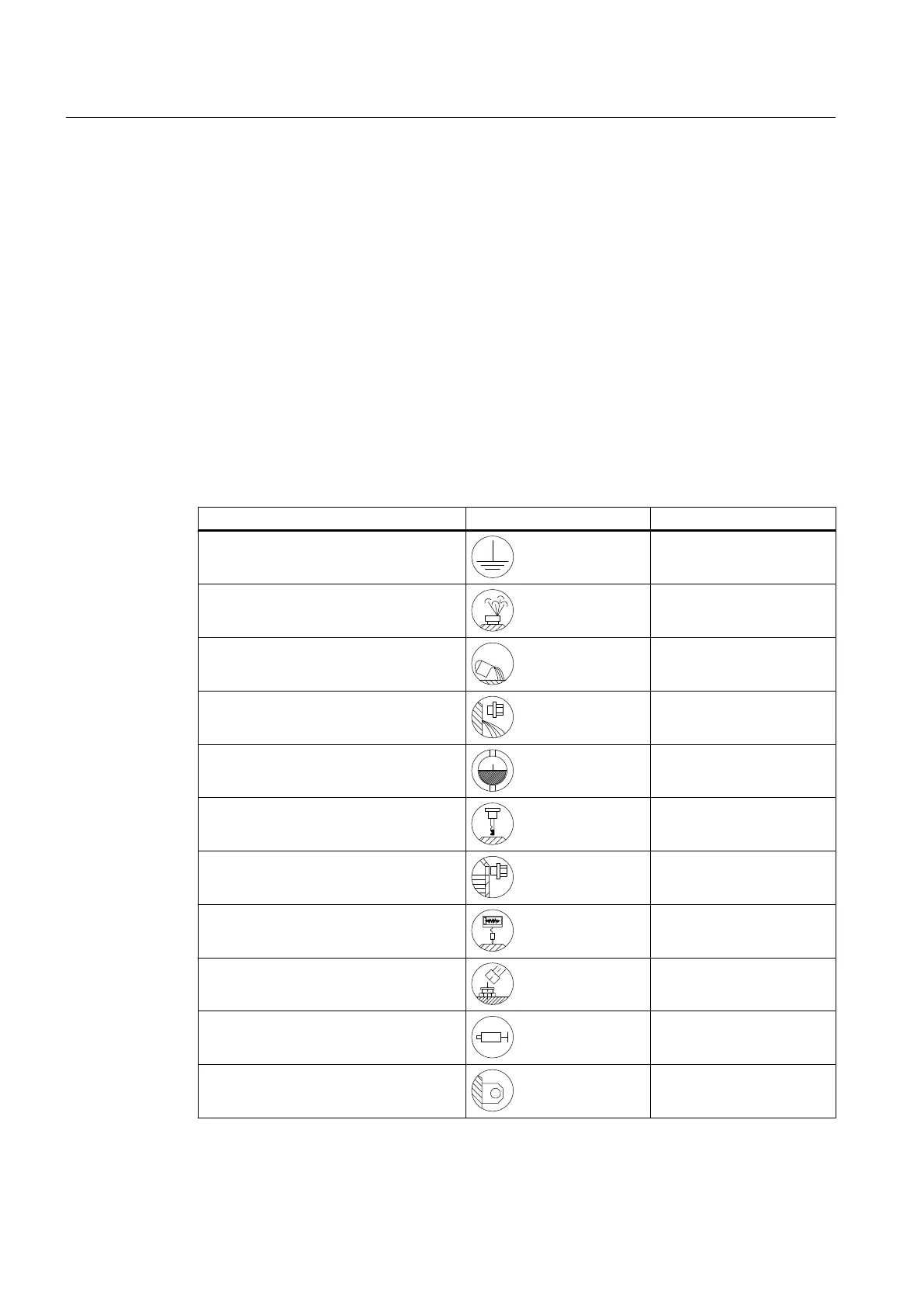
Table 2-1 Symbols and markings
Points labelled on the gear unit Symbol Coloured markings
Earth connection point
Air relief point yellow
Oil filling point yellow
Oil draining point white
Oil level indicator red
Oil level measurement red
Oil overflow
Connection point for vibration monitoring
Lubrication point red
Apply grease
Lifting eye
Safety instructions
2.3 General information
Gear unit 5118en
14 Operating Instructions 10/2017
 Loading...


