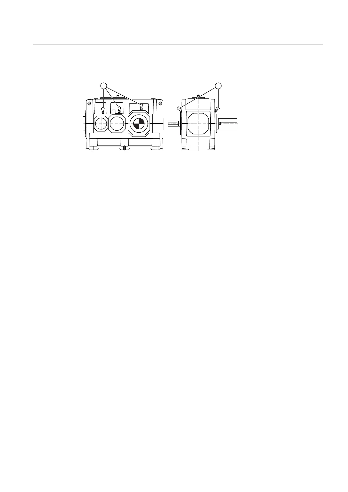
The following diagram shows bearing monitoring using a Pt 100 resistance thermometer:
① Pt 100 resistance thermometer
Figure 3-14 Bearing monitoring using a Pt 100 resistance thermometer
Further information
Further information and a detailed illustration of the gear unit and the position of the mounted
components can be found in the dimension drawing in the complete documentation for the
gear unit.
Further information about bearing monitoring using a Pt 100 resistance thermometer (such as
control instructions) and the technical data can be found in the operating instructions for the
Pt 100 resistance thermometer and in the list of equipment in the complete documentation for
the gear unit.
3.13.2 Bearing monitoring by shock-pulse transducer
Depending on the order specification, the gear unit can be equipped with measuring nipples
for monitoring the bearings.
These measuring nipples are used to attach shock-pulse transducers through a fast-release
coupling; they are located on the housing close to the bearings to be monitored.
Description
3.13 Bearing monitoring
Gear unit 5118en
Operating Instructions 10/2017 39