Using the telemetric measuring system you can transfer the measured values from a rotating
gearbox shafts contactlessly.
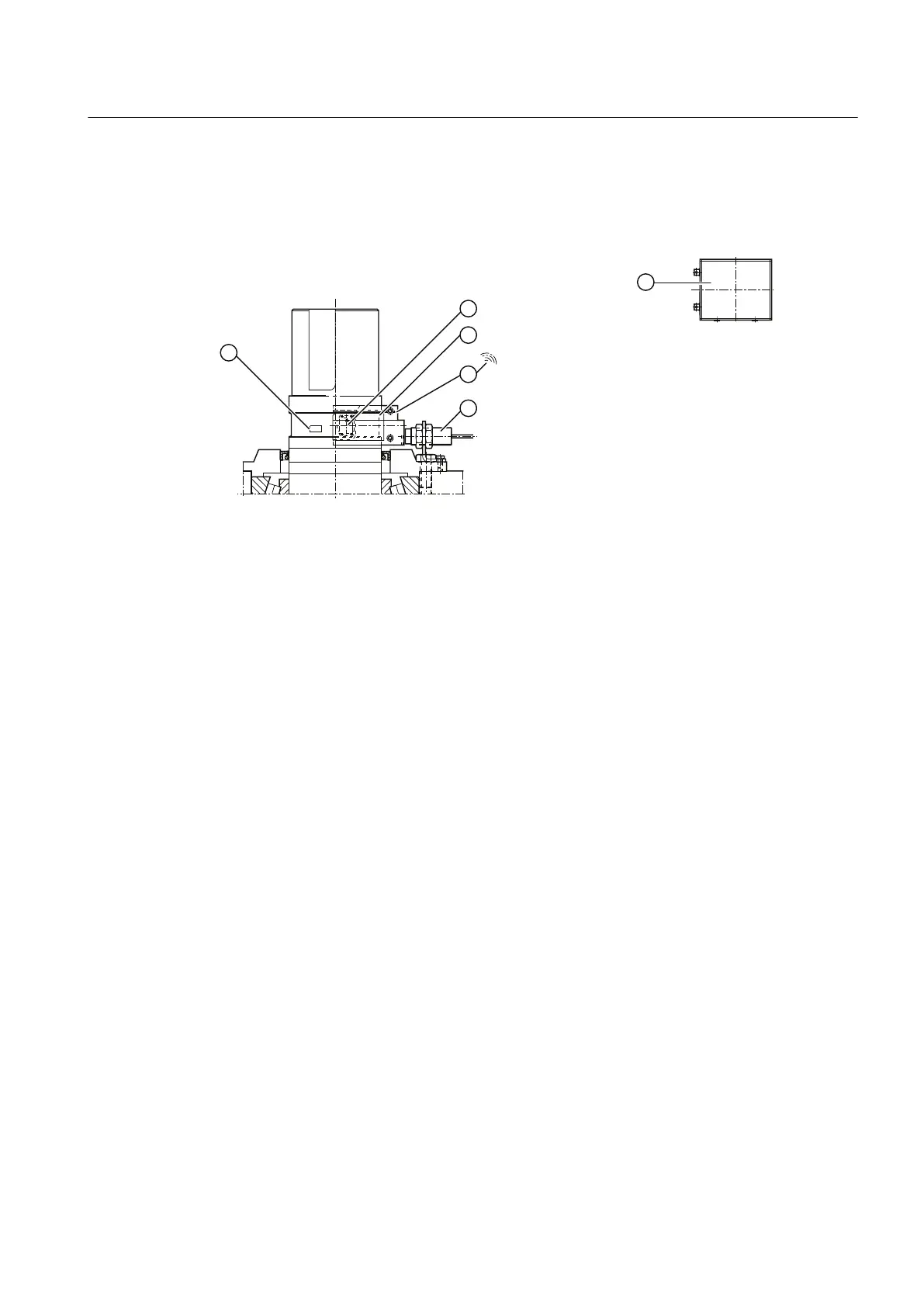
The following diagram shows a telemetric measuring system to monitor the torque:
① Strain gauges (glued to the shaft) ④ Slot with transmit antenna
② Measuring amplifier IS ⑤ Antennae inductive IS (energy supply head)
③ Rotor ring ⑥ Receiver IS
Figure 3-19 Telemetric measuring system to monitor the torque
Further information
You will find further information, a detailed illustration of the gear unit and the position of the
mounted components in the dimension drawing in the complete documentation for the gear
unit.
You will find further information on the torque monitoring system, such as control notes and
technical data, in the operating instructions for the torque monitoring system and in the list of
equipment, which are part of the complete documentation of the gear unit.
3.16 Gear unit monitoring "Condition Monitoring"
Depending on the order specification, the gear unit can be equipped with a complete remote
diagnostic system. This monitoring system "Condition Monitoring" includes a complete
diagnostic system and is coordinated with the customer depending on the specific order.
The gear unit monitoring "Condition Monitoring" can be prepared for the following
measurements and monitoring functions:
● Bearing temperature measurement in the area of the rolling-contact bearings
● Oil sump temperature measurement
● Speed monitoring at the output
Description
3.16 Gear unit monitoring "Condition Monitoring"
Gear unit 5118en
Operating Instructions 10/2017 43