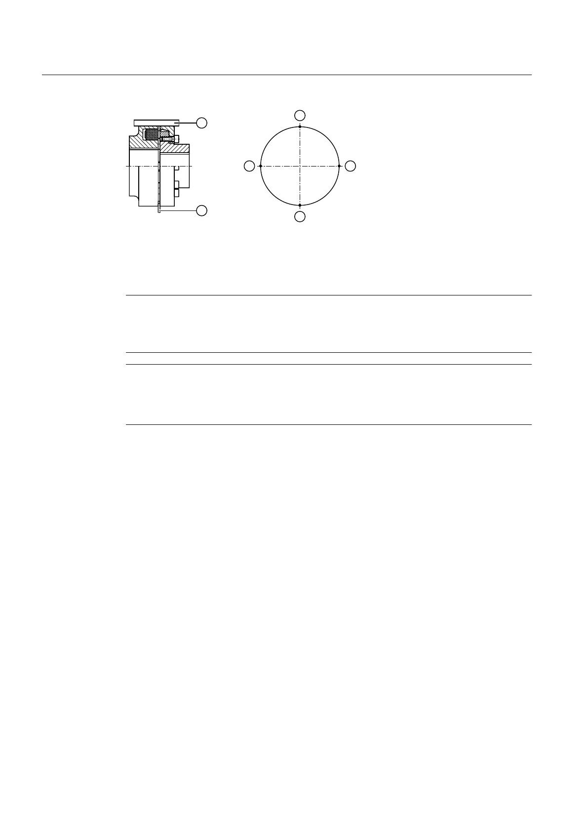
① Ruler ③ Measuring points
② Feeler gauge
Figure 5-8 Alignment process based on the example of a flexible coupling
Note
It is advisable to insert shims or metal sheets under the mounting feet in order to align the drive
components in the vertical direction. It is helpful to use support paws with adjusting screws on
the foundation to adjust the drive components laterally.
Note
Gear unit with motor bell housing
Couplings do not have to be aligned if the gear unit and motor are connected through a motor
bell housing.
Further information
You can find additional information about the permissible alignment errors for Flender
couplings in the complete documentation for the gear unit.
If couplings from other manufacturers are to be used, then, specifying the radial loads that
occur, ask the manufacturer which alignment errors are permissible.
5.5 Connecting components
5.5.1 Gear units with mounted components
Depending on the order specification, the gear unit can be equipped with various components.
Connect the closed-loop control and open-loop control electrical devices corresponding to the
specifications of the device supplier.
Assembly
5.5 Connecting components
Gear unit 5118en
68 Operating Instructions 10/2017