5.4 Couplings
Introduction
The coupling parts might become misaligned as a result of:
● Failure to accurately align the parts during assembly
● During operation of the system:
– Due to thermal expansion
– Due to shaft deflection
– Due to machine frames that are too soft
NOTICE
Damage or destruction of the coupling through incorrect alignment
Refer to the coupling operating instructions for the maximum permissible displacements.
Under no circumstances may these values be exceeded in operation.
Angular and radial displacement might occur simultaneously. Make sure that the total value
of both displacements does not exceed the maximum permissible angular or radial
displacement value.
If couplings from other manufacturers are to be used, then, specifying the radial loads that
occur, ask the manufacturer which alignment errors are permissible.
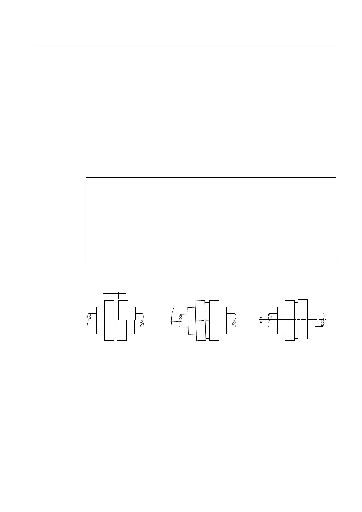
The following diagram shows the possible displacements:
5DGLDOPLVDOLJQPHQW
˂.U
$QJXODUPLVDOLJQPHQW
˂.Z
/DWHUDOPLVDOLJQPHQW
˂.D
˂.D
˂.Z
˂.U
Figure 5-7 Possible displacements
Alignment
Alignment must be carried out in two axis planes that are vertical with respect to one another.
This is possible using rulers (radial offset) and feeler gauges (angular offset) as shown in the
diagram. You will achieve a greater degree of alignment accuracy by using a dial gauge or
laser alignment system.
The diagram below shows the alignment process based on the example of a flexible coupling:
Assembly
5.4 Couplings
Gear unit 5118en
Operating Instructions 10/2017 67