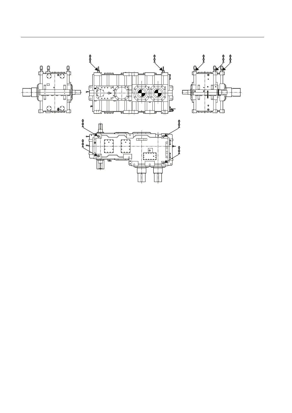
Figure 4-5 Position of the attachment points for gear units of type H3SX
Drive units with additional components mounted on the gear unit (such as drive motor,
coupling, etc.) may require an extra attachment point owing to the displacement in the centre
of gravity caused by the mounted components.
Further information
Further information, a detailed illustration of the gear unit and the position of the attachment
points can be found in the dimension drawings in the complete documentation for the gear unit.
Application planning
4.3 Attachment points
Gear unit 5118en
50 Operating Instructions 10/2017