Note
To prevent the formation of condensation, make sure that the cooling coil is fully immersed in
the oil.
Improper use can damage the cooling coil. Be sure to take the following precautions:
● Make sure that the cooling water pressure does not exceed 8 bar.
The direction of water flow through the gear unit is optional.
● Make sure that the ends of the cooling coil are not twisted and that the reducer screws are
not removed.
● If there is a risk of freezing temperatures, drain the cooling water out of the coil and blow
the coil out with compressed air to remove any water residue.
● Use a suitable cooling water flow regulator (e.g. a pressure reducing valve or an appropriate
isolation valve) in order to prevent excessive water pressure at the cooling water inlet.
WARNING
Risk of eye injury from compressed air
Water residue and dirt particles can cause damage to eyes.
Wear suitable safety goggles.
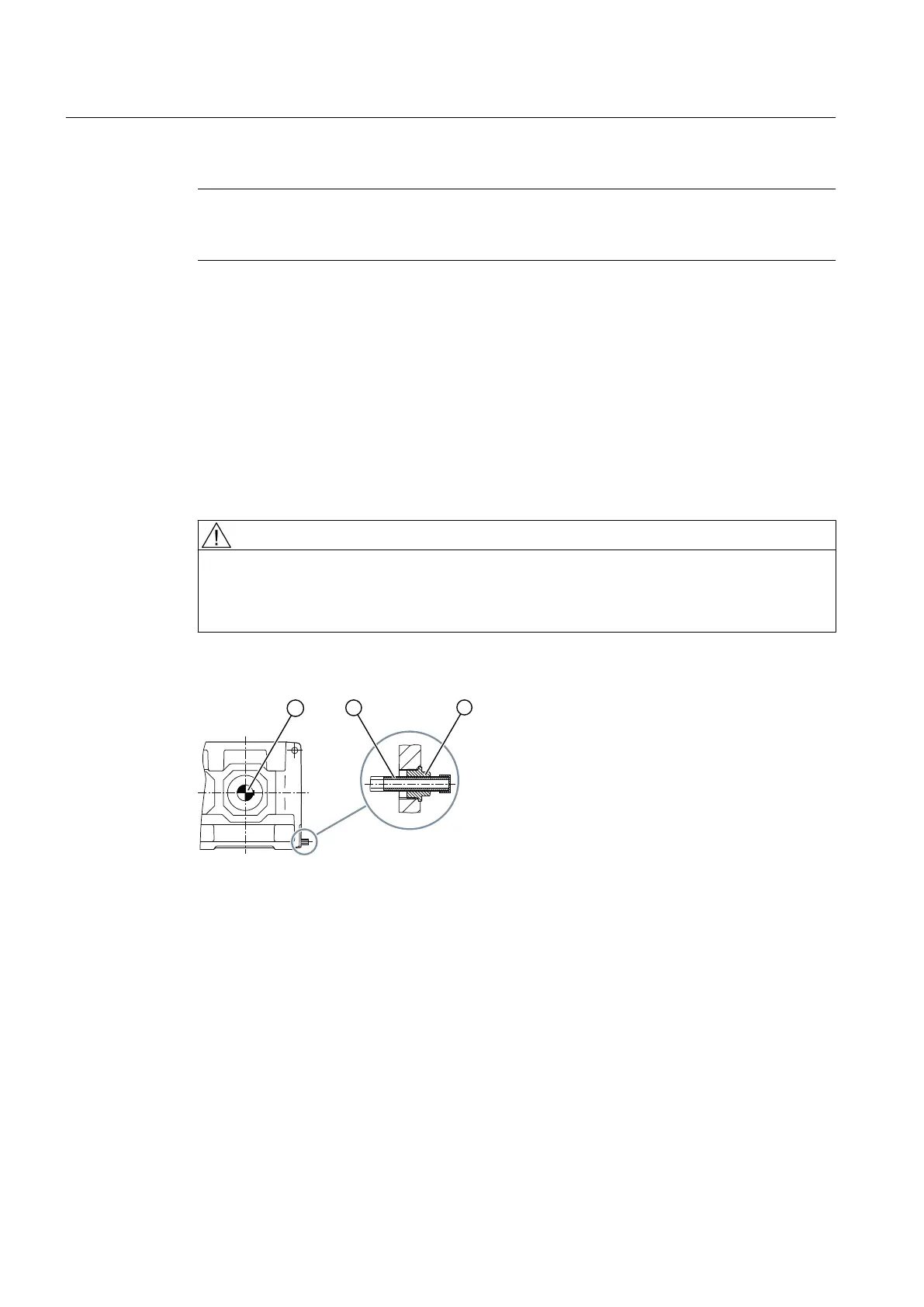
The diagram below shows the cooling coil connections:
① Output shaft ③ Reducer screw
② Cooling water connection
Figure 3-10 Cooling coil connections
Further information
For further information and a detailed illustration of the gear unit and the connection
dimensions, please refer to the dimension drawings in the complete gear unit documentation.
The required cooling water flow rate and the maximum permissible inlet temperature can be
found in the separate data sheet, the list of equipment or the dimension drawing in the complete
documentation for the gear unit.
Description
3.7 Cooling
Gear unit 5118en
32 Operating Instructions 10/2017