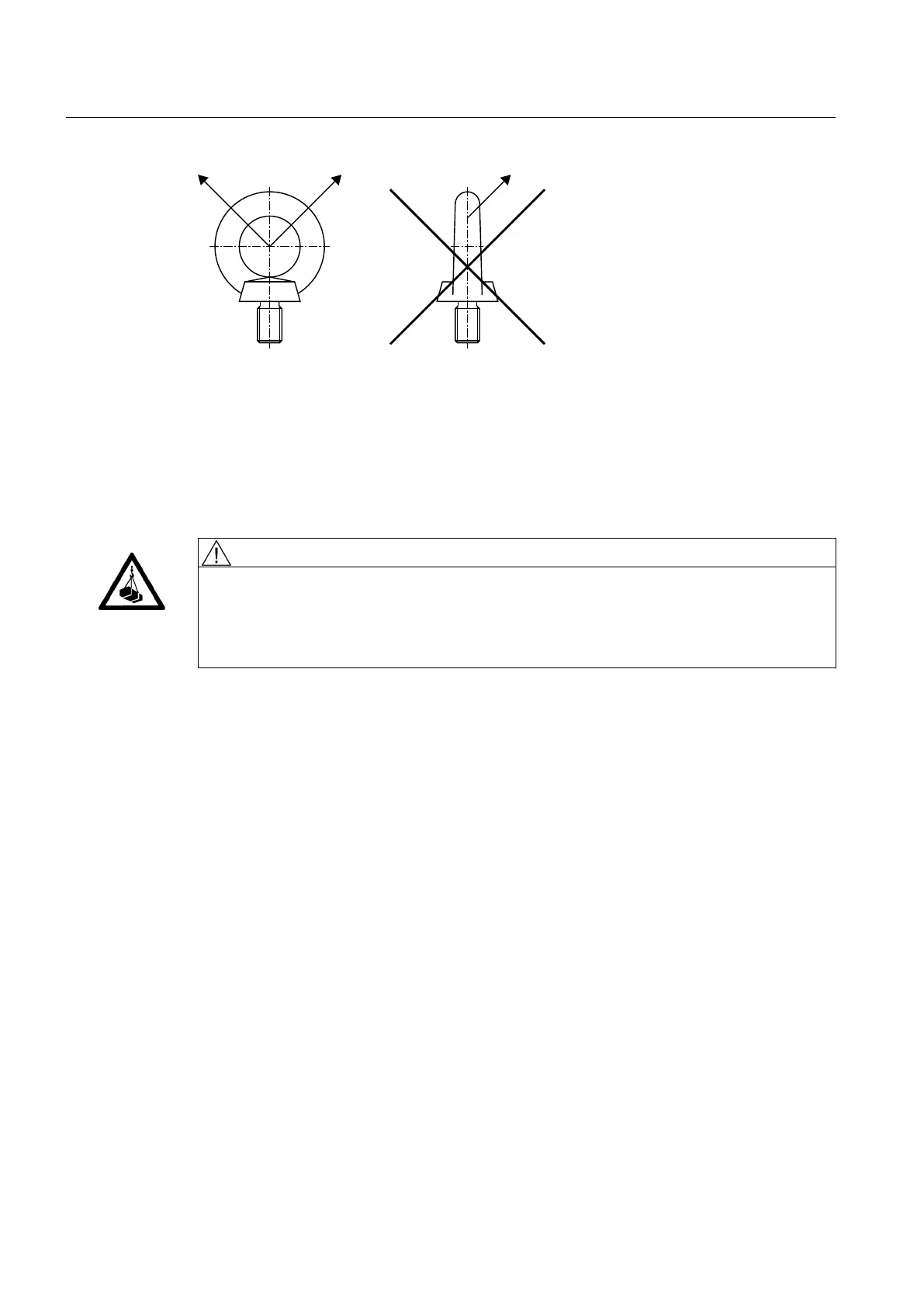
A Permitted shear pulling in direction of eye plane (maximum angle of 45°)
B Non-permitted lateral pulling contrary to direction of eye plane
Figure 4-2 Shear and lateral pulling when using eye bolts
Position of attachment points
DANGER
Falling load
There is a risk of fatal injury from falling loads if these have not been securely attached to the
lifting equipment.
Do not use the lifting eyes at the upper part of the gear unit to lift the complete gear unit.
The diagram below shows the position of the attachment points for gear units of type
H2SH 24 (SOND 622):
Application planning
4.3 Attachment points
Gear unit 5118en
48 Operating Instructions 10/2017