0
0
r
$
%
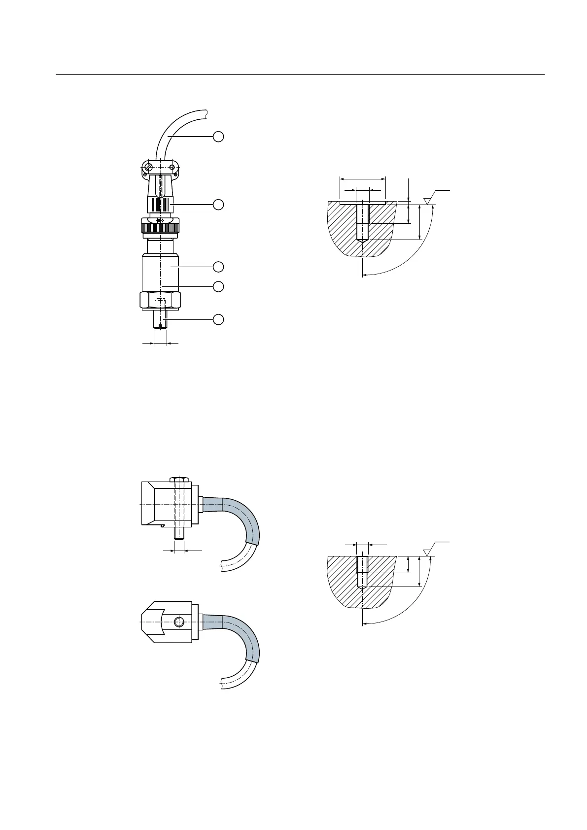
① Shielded cable (oil-proof) ④ Sensitivity specification
② MIL-spec connector ⑤ Set screw
③ Acceleration sensor
Figure 3-16 Fully assembled acceleration sensor (A), and threaded connector (B) for variants 1 to 4
The following diagram shows the fully assembled acceleration sensor (C), and the threaded
connector (D) for variants 5A and 5B:
Figure 3-17 Fully assembled acceleration sensor (C), and the threaded connector (D) for variants 5A
and 5B
Description
3.13 Bearing monitoring
Gear unit 5118en
Operating Instructions 10/2017 41