Further information
Further information and a detailed illustration of the gear unit with attached sensors can be
found in the dimension drawing in the complete documentation for the gear unit.
Further information about the sensors can be found in the operating instructions for the sensors.
3.14 Speed encoder
Depending on the order specification, an incremental speed encoder can be fitted.
Customers must establish the wiring and provide the evaluation unit required.
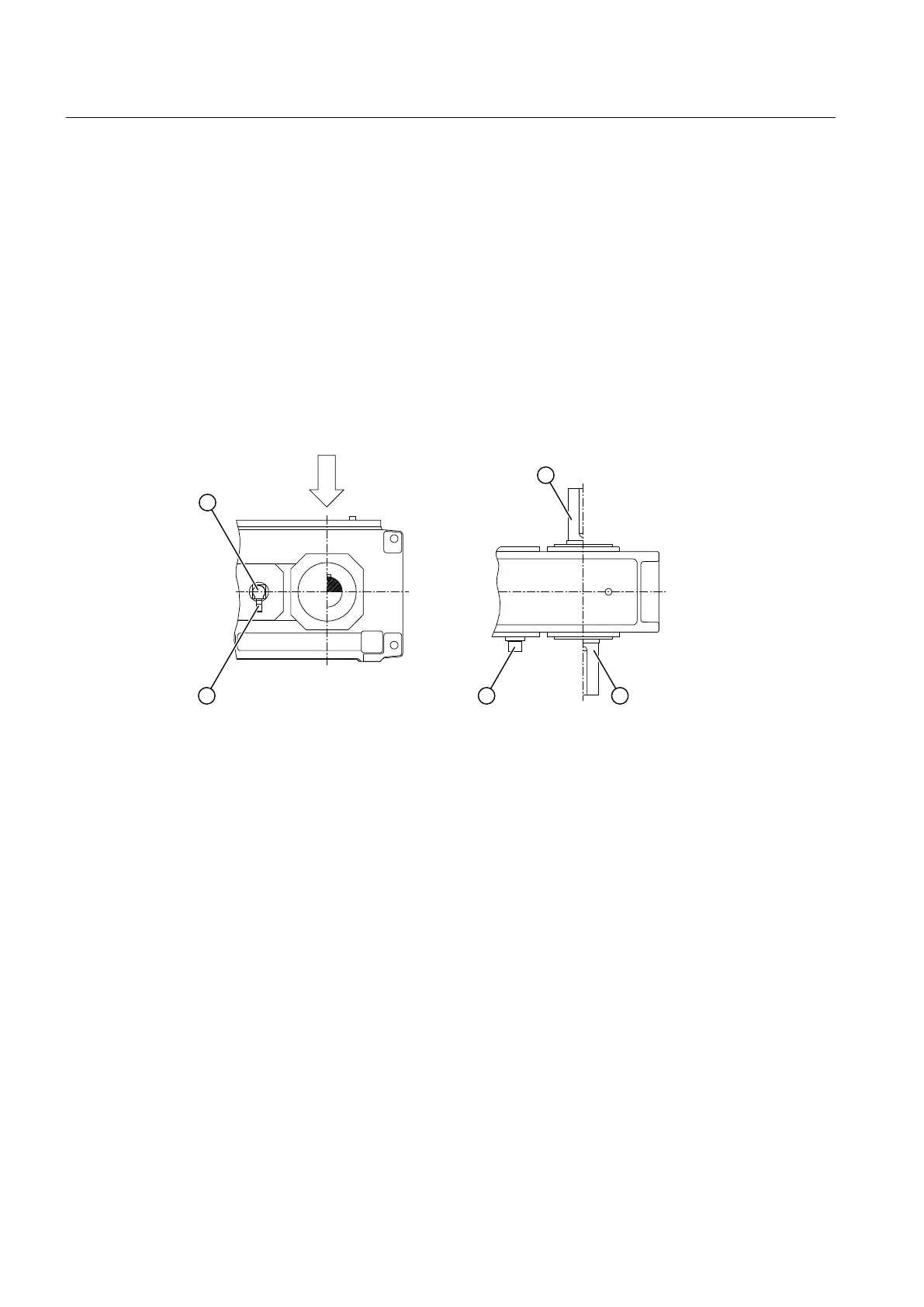
The following diagram shows a speed encoder:
① Incremental speed encoder ③ Output
② 12-pole brass connector
Figure 3-18 Speed encoder
Further information
You will find further information, a detailed illustration of the gear unit and the position of the
mounted components in the dimension drawing in the complete documentation for the gear
unit.
You can find further information about the speed encoder (such as control instructions) and
technical data, in the speed encoder operating instructions and in the equipment list provided
in the complete gear unit documentation.
3.15 Torque monitoring system
Depending on the order specification, the gear unit can be equipped with a telemetric
measuring system to monitor the torque.
Description
3.14 Speed encoder
Gear unit 5118en
42 Operating Instructions 10/2017



 To Next Page