Further information
Further information about the oil level indicator and checking the oil can be found in the
operating instructions BA 7300 in the complete documentation for the gear unit.
Further information and a detailed illustration of the gear unit and the position of the mounted
components can be found in the dimension drawing in the complete documentation for the
gear unit.
3.11 Oil-level monitoring system
Introduction
Depending on the order specification, the gear unit can be equipped with an oil-level monitoring
system using a filling-level limit switch.
The oil-level monitoring system has been designed to check the oil level when the gear unit is
at a standstill before it starts.
Mounting position
When using an oil-level monitoring system it is especially important to ensure that the gear
unit is in a horizontal mounting position.
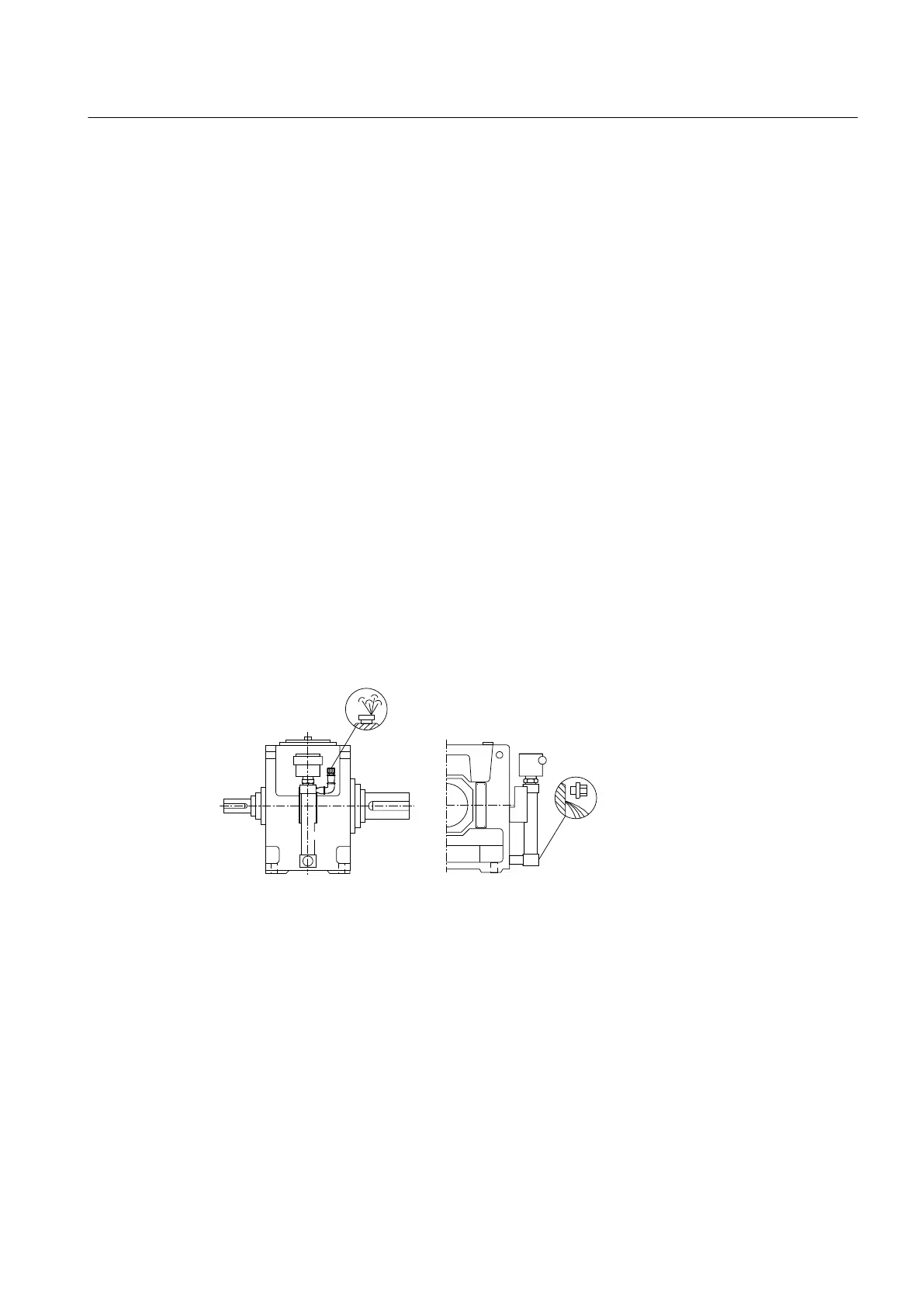
The diagram below shows the oil-level monitoring system for the gear unit:
Figure 3-12 Oil-level monitoring system for gear units, types H... and B...
Further information
Further information and a detailed illustration of the gear unit and the position of the mounted
components can be found in the dimension drawing in the complete documentation for the
gear unit.
Further information about oil level monitoring, control instructions and the technical data can
be found in the operating instructions for the oil level monitor, in the list of equipment and in
the separate data sheet in the complete documentation for the gear unit.
Description
3.11 Oil-level monitoring system
Gear unit 5118en
Operating Instructions 10/2017 37