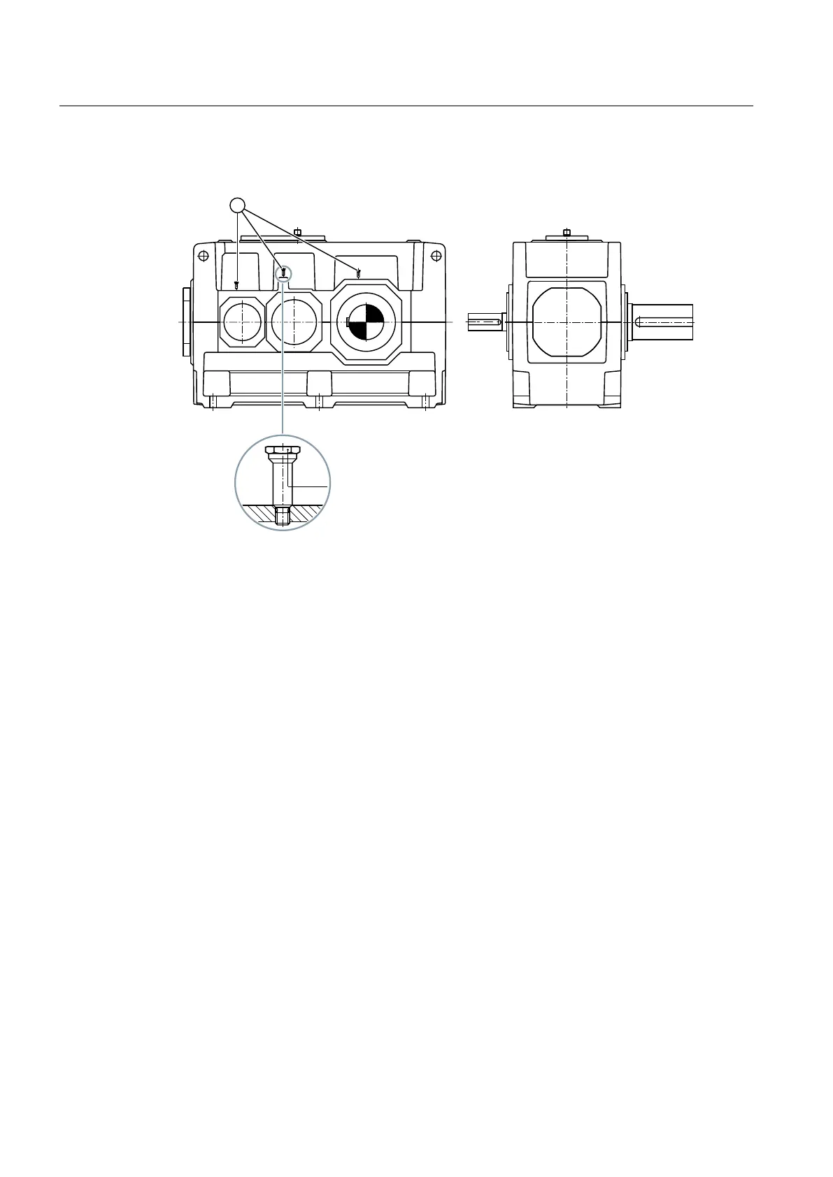
The following diagram shows a bearing monitoring system that uses a shock-pulse transducer:
① Shock-pulse transducer
Figure 3-15 Bearing monitoring using a shock-pulse transducer
Further information
Further information and a detailed illustration of the gear unit and the position of the mounted
components can be found in the dimension drawing in the complete documentation for the
gear unit.
3.13.3 Bearing monitoring by acceleration sensor
Depending on the order specification, the gear unit can be supplied with threaded holes in
which acceleration sensors can be inserted. These threaded holes have an M6 or M8 thread
depending on the variant.
The following diagram shows the fully assembled acceleration sensor (A), and the threaded
connector (B) for variants 1 to 4:
Description
3.13 Bearing monitoring
Gear unit 5118en
40 Operating Instructions 10/2017