To align the gear unit by its alignment surface, proceed as follows:
1. For the precise position of the alignment surfaces, refer to the dimension drawings in the
complete documentation.
2. Note the values inscribed in the alignment surfaces.
3. Use these surfaces as a guide for aligning the gear unit horizontally to ensure that it will
run smoothly.
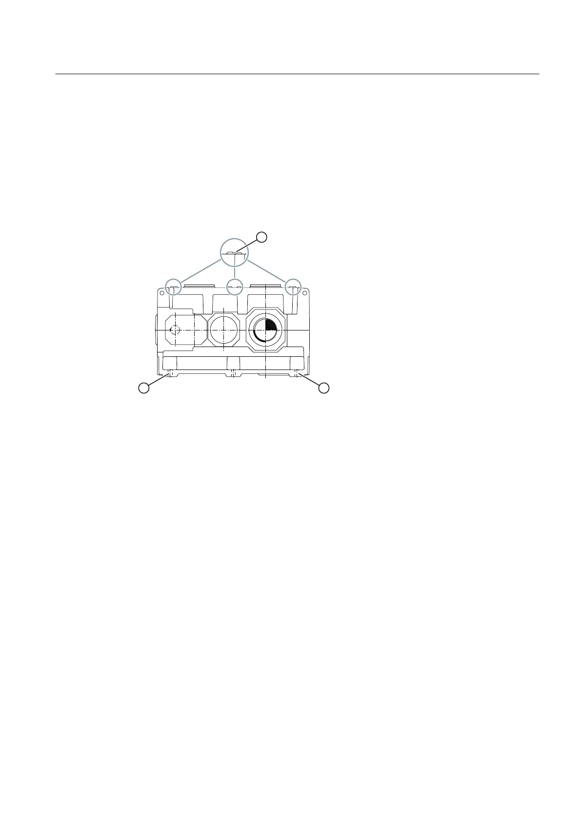
The following diagram shows the alignment surfaces and alignment thread at the gear units:
① Alignment surfaces ② Alignment thread
Figure 5-3 Alignment surfaces and alignment thread at the gear unit
Further information
Further information and the precise position of the alignment thread are provided in the
dimension drawing in the overall gear unit documentation.
Tools
The following tools are needed to perform the final fine alignment (Page 67) work on the shaft
axes of the gear unit and the equipment installed on the input and output sides.
● Rulers
● Spirit level
● Dial gauge
● Feeler gauge etc.
Once the gear unit is finely aligned, tighten the foundation bolts and check the settings again.
Record the alignment dimensions and keep the report in a safe place together with these
operating instructions.
Assembly
5.3 Gear unit assembly
Gear unit 5118en
Operating Instructions 10/2017 61
 Loading...


