FLUXUS F808, F809 6 Installation of FLUXUS F808
38 UMFLUXUS_F808_8091V1-2-1EN, 2019-08-23
6.6.3 Connection to the junction box
The transducers and the extension cable are connected via the terminal board KFM1. The terminal board has to be in-
stalled into a junction box (by the customer) approved for the use in explosive atmospheres.
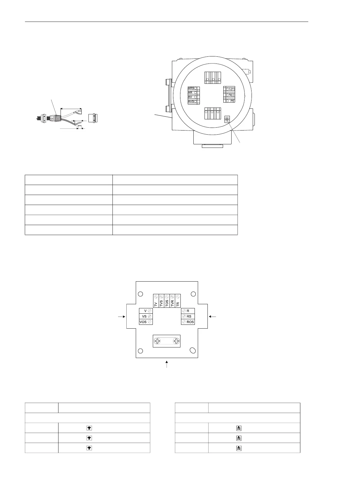
• Connect the transducer cable to the terminals of the junction box (see Fig. 6.15, Tab. 6.10 and Tab. 6.11).
Fig. 6.14: Connection of the extension cable
Tab. 6.9: Terminal assignment (transmitter, KL 4)
terminal connection (extension cable)
AV white or marked cable (core)
AVS white or marked cable (internal shield)
ARS brown cable (internal shield)
AR brown cable (core)
equipotential bonding terminal external shield
Fig. 6.15: Terminal board KFM1
Tab. 6.10: Terminal assignment (terminal board KFM1)
terminal connection (transducer cable) terminal connection (transducer cable)
terminal strip KL1 terminal strip KL2
V transducer (signal) R transducer (signal)
VS transducer (inner shield) RS transducer (inner shield)
VOS transducer (external shield) ROS transducer (external shield)
transducers
KL1
KL3
KL4 KL2
equipotential bonding terminal
(transducers)
70 mm
20 mm
10 mm
extension cable
external shield
KL1 KL2
KL3
transducer cable transducer cable
extension cable
 Loading...


