6 Installation of FLUXUS F808 FLUXUS F808, F809
UMFLUXUS_F808_8091V1-2-1EN, 2019-08-23 49
6Installation of FLUXUS F808
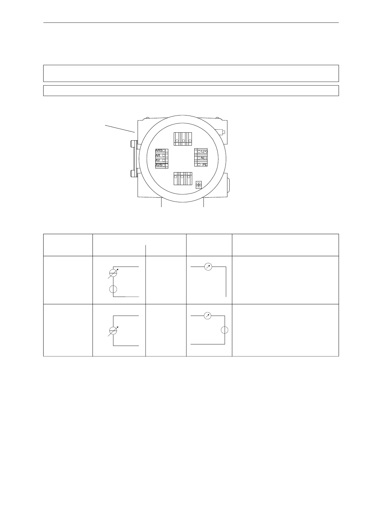
6.9 Outputs
For the connection of the output cable to the transmitter, see box "Cable connection", p. 47,
Fig. 6.25
and
Tab. 6.20
.
Attention! Observe the "Safety instructions for the use in explosive atmospheres" (see document SIFLUXUS,
SIFLUXUS_808_FM,SIFLUXUS_808_F2 and SIFLUXUS_1N62).
Attention! The outputs may only be connected to a low voltage circuit (max. 30 V AC or 42 V DC against earth).
Fig. 6.25: Connection of the outputs
Tab. 6.20: Circuits of the outputs
output transmitter
external circuit
remark
internal circuit connection
active current
loop I1: 2 (+)
KL3
I1: 1 (-)
R
ext
< 500 Ω
passive current loop
I1: 1 (-)
KL3
I1: 2 (+)
U
ext
=
4…24 V
U
ext
> 0.021 A · R
ext
[Ω] + 4 V
example:
U
ext
= 12 V
R
ext
≤ 380 Ω
The number, type and connections of the outputs are customized.
R
ext
is the sum of all ohmic resistances in the circuit (e.g. resistance of the conductors, resistance of the amperemeter/voltmeter).
KL1
KL3
KL4 KL2
outputs
+
-
mA
+
-
mA
U
ext
-
+

 Loading...


