6 Installation of FLUXUS F808 FLUXUS F808, F809
UMFLUXUS_F808_8091V1-2-1EN, 2019-08-23 29
6Installation of FLUXUS F808
6.5 Connection of the transducers to the transmitter F808**-A1
It is recommended to run the cables from the measuring point to the transmitter before connecting the transducers to
avoid load on the connectors.
For the connection of the transducer cable to the transmitter see section 6.5.1.
For the connection of the extension cable to the transmitter see section 6.5.2.
For the connection of the transducer cable to the junction box see section 6.5.3.
For the connection of the extension cable to the junction box see section 6.5.4.
6.5.1 Connection of the transducer cable to the transmitter
6.5.1.1 Transducer cable with stainless steel conduit and stripped cable ends
• The transmitter has 1 cable gland for the connection of the transducers.
• Remove the left blind plug for the connection of the transducer cable (see Fig. 6.5).
• Open the cable gland. The compression part remains in the cap nut.
• Push the transducer cable through the cap nut and the compression part.
• Press the cap nut with the compression part on the cable until the thin rim of the compression part is flush with the exter-
nal cable jacket.
• Insert the transducer cable into the housing.
• Tighten the gasket ring side of the basic part into the transmitter housing.
• Fix the cable gland by screwing the cap nut onto the basic part.
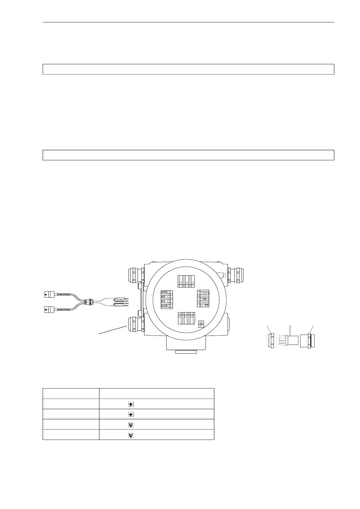
• Connect the transducer cable to the terminals of the transmitter (see Fig. 6.5 and Tab. 6.1).
Note!
If transducers are replaced or added, the sensor module also has be replaced or added (see section 6.11).
Attention! Observe the "Safety instructions for the use in explosive atmospheres" (see document SIFLUXUS).
Fig. 6.5: Connection of the transducer cable
Tab. 6.1: Terminal assignment (transmitter, KL4)
terminal connection (transducer cable)
AV transducer (brown cable, marked white)
AVS transducer (red cable)
ARS transducer (red cable)
AR transducer (brown cable)
transducers
KL1
KL3
KL4 KL2
transducer cable
cable gland
cap nut
compression part basic part

 Loading...


