FLUXUS F808, F809 6 Installation of FLUXUS F808
32 UMFLUXUS_F808_8091V1-2-1EN, 2019-08-23
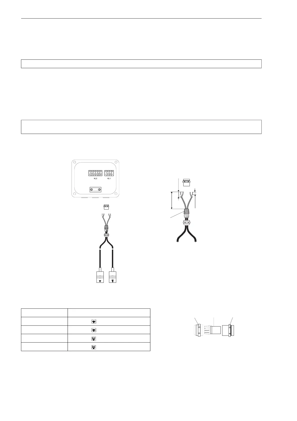
6.5.3 Connection of the transducer cable to the junction box
6.5.3.1 Transducer cable with plastic cable jacket and stripped cable ends
• Remove the right blind plug for the connection of the transducer cable (see Fig. 6.8).
• Open the cable gland. The compression part remains in the cap nut.
• Push the transducer cable through the cap nut and the compression part.
• Prepare the transducer cable.
• Shorten the external shield and brush it back over the compression part.
• Tighten the gasket ring side of the basic part tightly into the junction box.
• Insert the transducer cable into the junction box.
• Fix the cable gland by screwing the cap nut onto the basic part.
• Connect the transducer cable to the terminals of the junction box (see Fig. 6.8 and Tab. 6.4).
Attention! Observe the "Safety instructions for the use in explosive atmospheres" (see document SIFLUXUS).
Attention! For good high frequency shielding, it is important to ensure good electrical contact between the exter-
nal shield and the cap nut (and thus to the junction box).
Fig. 6.8: Transducer cable with plastic cable jacket and stripped cable ends
Tab. 6.4: Terminal assignment (junction box, KL1)
terminal connection (transducer cable)
V transducer (core)
VS transducer (inner shield)
RS transducer (inner shield)
R transducer (core)
Fig. 6.9: Cable gland
100 mm
20 mm
10 mm
external shield,
brushed back
cap nut
compression part basic part

 Loading...


