6 Installation of FLUXUS F808 FLUXUS F808, F809
UMFLUXUS_F808_8091V1-2-1EN, 2019-08-23 31
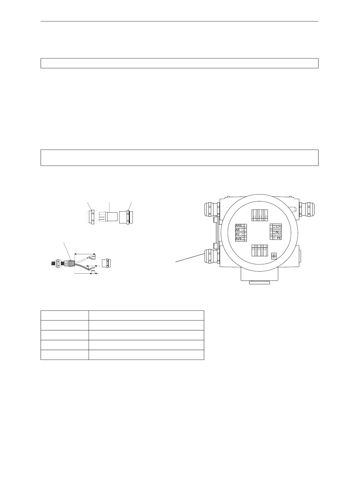
6.5.2 Connection of the extension cable to the transmitter
• The transmitter has 1 cable gland for the connection of the transducers.
• Remove the left blind plug for the connection of extension cable (see Fig. 6.7).
• Open the cable gland. The compression part remains in the cap nut.
• Push the transducer cable through the cap nut and the compression part.
• Prepare the extension cable.
• Press the cap nut with the compression part on the cable until the thin rim of the compression part is flush with the exter-
nal cable jacket.
• Cut the external shield and brush it back over the compression part.
• Insert the extension cable into the housing.
• Tighten the gasket ring side of the basic part into the housing of the transmitter.
• Fix the cable gland by screwing the cap nut onto the basic part.
• Connect the extension cable to the terminals of the transmitter (see Fig. 6.7 and Tab. 6.3).
Attention! Observe the "Safety instructions for the use in explosive atmospheres" (see document SIFLUXUS).
Attention! For good high frequency shielding, it is important to ensure good electrical contact between the exter-
nal shield and the cap nut (and thus to the housing).
Fig. 6.7: Connection of the extension cable
Tab. 6.3: Terminal assignment (transmitter, KL4)
terminal connection (extension cable)
AV white or marked cable (core)
AVS white or marked cable (internal shield)
ARS brown cable (internal shield)
AR brown cable (core)
KL1
KL3
KL4 KL2
70 mm
20 mm
10 mm
extension cable
cable gland
external shield
cap nut
compression part basic part
transducers

 Loading...


