6 Installation of FLUXUS F808 FLUXUS F808, F809
UMFLUXUS_F808_8091V1-2-1EN, 2019-08-23 47
6Installation of FLUXUS F808
6.8 Power supply
6.8.1 FLUXUS F808**-A1, FLUXUS F808**-F2
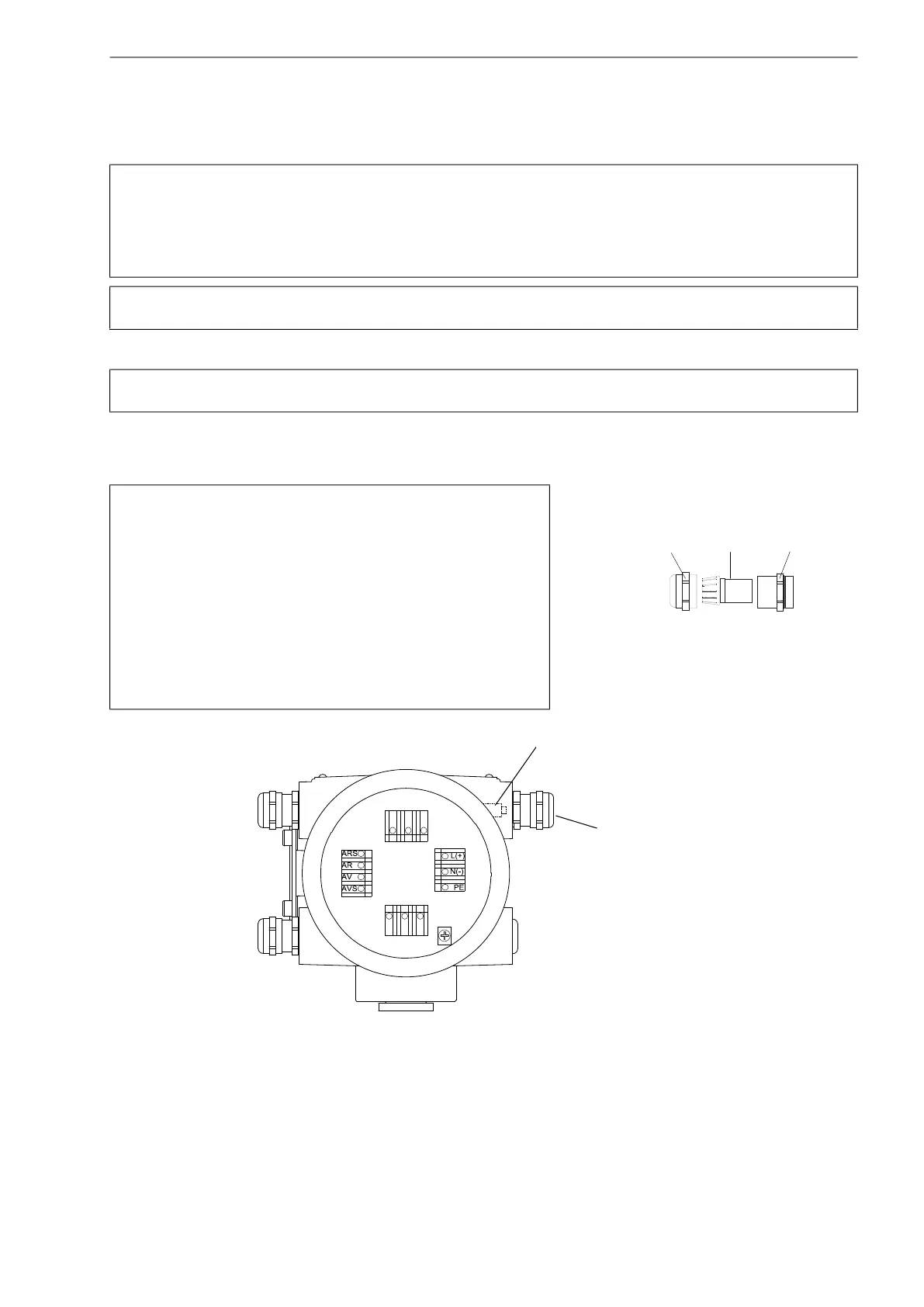
The external protective earth is connected to the equipotential bonding terminal on the transmitter housing. It always has
to be connected (see Fig. 6.23).
For the connection of the power cable to the transmitter, see box "Cable connection", Fig. 6.23 and Tab. 6.18
.
Attention! According to IEC 61010-1:2010, a switch has to be provided near the measuring instrument in the
building installation, easily accessible for the user and marked as a disconnection device for the mea-
suring instrument.
If the measuring instrument is used in an explosive atmosphere, the switch should be installed out-
side the explosive atmosphere. If this is not possible, the switch should be installed in the least haz-
ardous area.
Attention! The degree of protection of the transmitter will only be guaranteed if the power cable fits firmly and
tightly in the cable gland.
Attention! Observe the "Safety instructions for the use in explosive atmospheres" (see document SIFLUXUS
and SIFLUXUS_808_F2).
Cable connection
• Remove the blind plug from the transmitter for the connection of
the cable (if present).
• Prepare the cable with an M20 cable gland.
• Push the cable through the cap nut, the compression part and the
basic part of the cable gland.
• Insert the cable into the housing of the transmitter.
• Tighten the gasket ring side of the basic part into the housing of
the transmitter.
• Fix the cable gland by screwing the cap nut onto the basic part.
• Connect the cable to the terminals of the transmitter.
Fig. 6.23: Connection of the power supply
Fig. 6.22: Cable gland
cap nut
compression part
basic part
KL1
KL3
KL4 KL2
power supply
equipotential bonding
terminal

 Loading...


