FT-111(D) Panel Weighing Indicator, Technical Manual, Rev.1.0.0, May 2019 Page 20 of 146
4.6 Electrical Connections
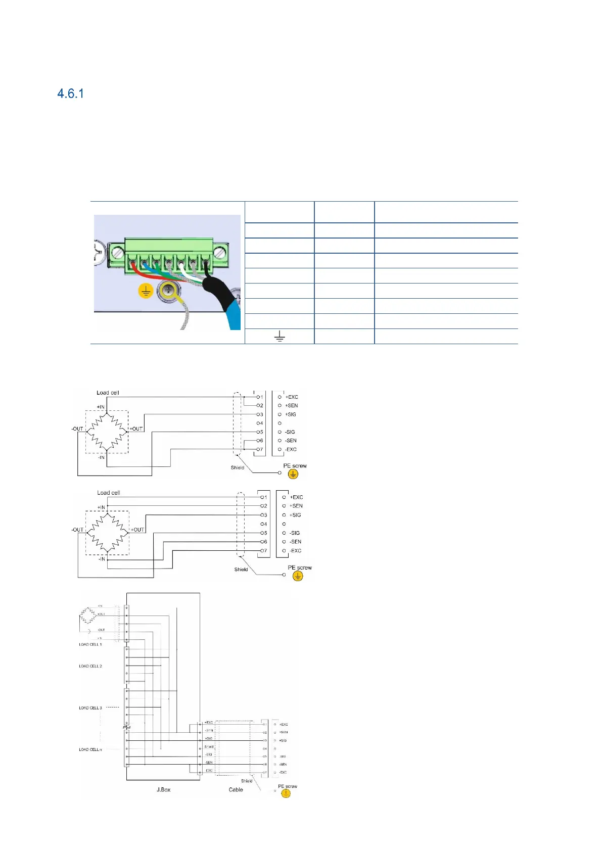
Analogue Load Cell Connection (Only FT-111)
To avoid damages, the load cell wiring should be made carefully before energizing the instrument. Load cell
connection schematics are in
Figure 4.3.
The same polarity sense and excitation pins of the load cell connector should be short circuited for 4-wire
installation. If you have junction box in your system, use 6 wire cable between indicator and the junction box,
and short circuit these pins in junction box for better performance as shown below.
Table 4-1 – Pin configuration of the analogue load cell terminal.
Protective ground connection of cable shields is done by;
Figure 4.3 – The analogue load cell and junction box connection.