FT-111(D) Panel Weighing Indicator, Technical Manual, Rev.1.0.0, May 2019 Page 27 of 146
The HUB connection cabling will be a direct connection as shown below:
Figure 4.16 - HUB connection
The PC connection cabling will be done via cross cable as shown below. IP address blocks and gateway address of
weighing indicator and PC should be the same in cross connection.
Figure 4.17 - Cross PC connection
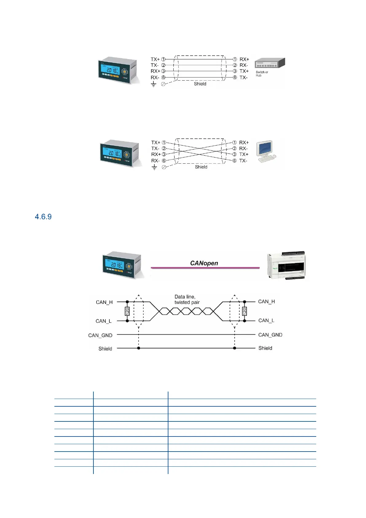
CANopn
CANopen connection is done with four wire as indicated below in Figure 4.18. The data line ends must be terminated with
120-ohm resistors.
Figure 4.18 - PLC Connection
CANopen Connector pin configuration (DB9M)