7 DIGITAL LOAD CELL (DLC)
7.1 Addressing Digital Load cells
IMPORTANT NOTE: You can connect all RC3D to the terminal and address them later.
The following diagram shows the recommended load cell addressing principle. Remember, if pair shift adjustment
is selected, 1 and 2, 3 and 4 etc. will be sectional pairs.
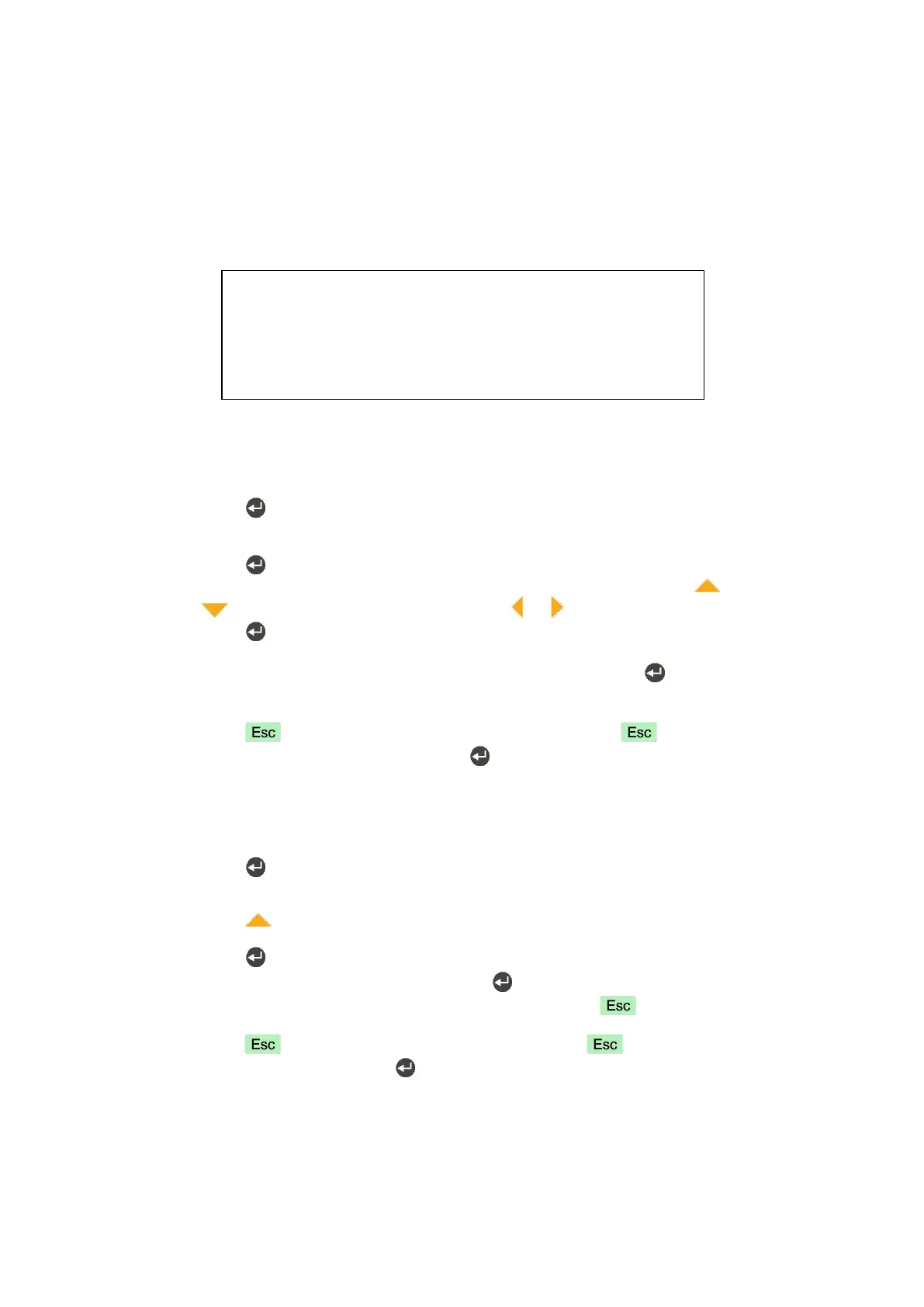
Figure 7.1 - The addressing principle of the digital load cells.
Addressing of RC3D digital load cells
1. Press key at the [ 533 ADDRESSING ] prompt to start the addressing.
2. At the [ WAIT ] prompt for a short time and then [ DLC NUMBER :01 ] message appears. Here 01 is the
address of the DLC.
3. Press key to enter the serial number of the DLC.
4. After the [ SERIAL: ] prompt, type the serial number value via pressing key to increase or
key to decrease the blanking digit and press or key to select digit.
5. Press key to start addressing the digital load cell. [ ADDRESSING DLC ] message will appears on
the display for 10 seconds while addressing is being performed.
6. The following DLC number seen on the display. You may press key to enter the serial
number and you may repeat from item 4 until all DLCs have been addressed.
7. [ 532 QUANTITY :XY ] message appears after addressing all load cells.
8. Press key to access to Shift adjustment block or press key until [ SAVE : YES ]
prompt seen on the display and press key to save the changes into the memory.
Manually Addressing of an invidual RC3D digital load cell
The manual addressing of load cell is done to change any load cell or to change the instrument without performing
shift adjustment and calibration.
1. Press key at the [ 533 ADDRESSING ] prompt to start the addressing.
2. At the [ WAIT ] prompt for a short time and then [ DLC NUMBER :01 ] message appears to indicate load
cell address.
3. Press key until appearing the address which the new load cell will install.
4. Connect the new load cell to junction box.
5. Press key to start address the load cell.
6. Enter the serial number of the load cell. Press key for addressing the load cell.
7. After the following DLC number seen on the display, then press key. [ 532 QUANTITY :XY ]
message appears.
8. Press key to access to Shift adjustment block or press key until [ SAVE : YES ] prompt
seen on the display and press key to save the changes into the memory.
Shift adjustment method
The shift adjustment is done to eliminate weight reading differences at placing the load on different positions on the
platform. The calibration is required after shift adjustment.
Each load cell or each sectional pair should be loaded for eccentricity adjustment. Individual shift adjustment is
used to eliminate errors in installations that have excessive eccentricity errors. Typical application of sectional
pairs is rolling loads on the platform like truck scales. Sectional pairs adjustment is more easy and faster.