FT-111(D) Panel Weighing Indicator, Technical Manual, Rev.1.0.0, May 2019 Page 85 of 146
9 SERIAL DATA OUTPUTS
FT-111 weighing indicator has RS232, RS485, RS422, USB and Ethernet interfaces. In this section, you will
find the data structure of different type of the data outputs via these serial ports. If, you transmit ASCII codes of
P(print), Z(zero), T(tare) or C(clear) letters to the serial port of FT-111; it will act like the related key is pressed.
9.1 Continuous Data Output
Continuous data output of the instrument is transmitted in the following data structure. The serial ports of FT-111 are
suitable for bi-directional communication.
CR (Carriage return) and LF (Line feed) codes can be enabled or disabled from response.
CHK (Checksum) can be enabled or disabled from both command and response and only continuous data output can be
programmed for more than one interface.
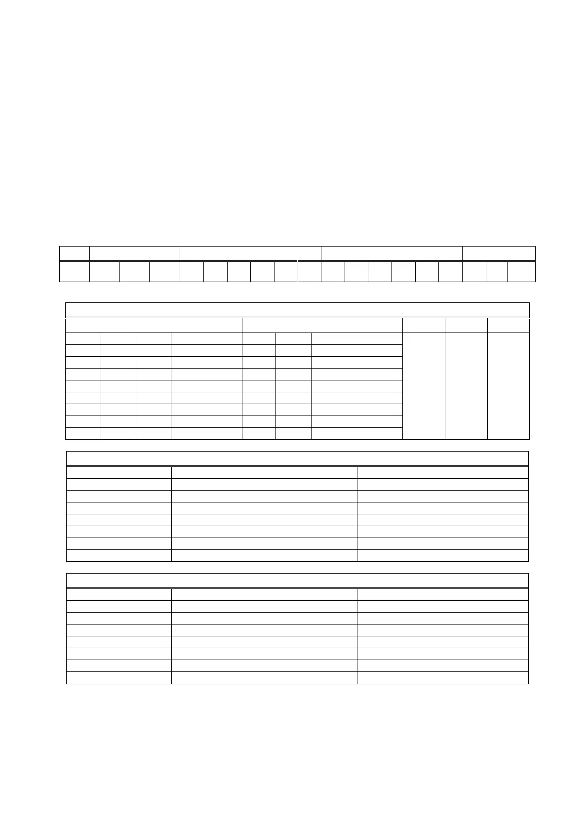
The data format of continuous data output is;
CHK (Checksum) = 0 – ( STX + STATUS A + ..... + LF )
Error Messages: UNDER, OVER, A.OUT, L-VOLT and TILT are represented in Indicated data fields.
Note: The weight data is represented with right aligned and the error messages are represented with left aligned.