FT-111(D) Panel Weighing Indicator, Technical Manual, Rev.1.0.0, May 2019 Page 28 of 146
EtherNET/IP
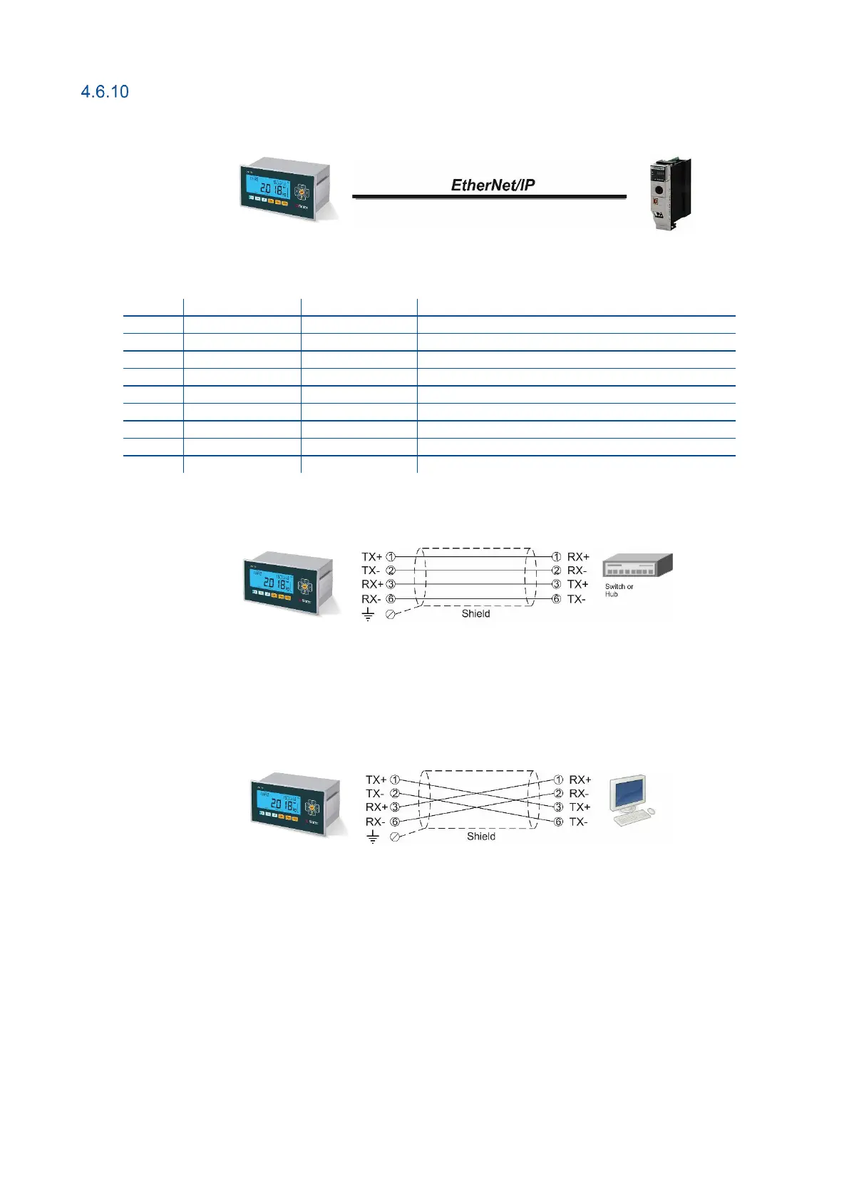
Figure 4.19 – PLC Connection
EtherNet/IP Connector pin configuration (RJ45)
Differential Ethernet transmit data +
Differential Ethernet transmit data −
Differential Ethernet receive data +
Differential Ethernet receive data −
The HUB connection cabling will be a direct connection as shown below:
Figure 4.20 - HUB connection
The PC connection cabling will be done via cross cable as shown below. IP address blocks and gateway address of
weighing indicator and PC should be the same in cross connection.
Figure 4.21 - Cross PC connection
Pin configuration of digital input and output connector is described in Fehler! Verweisquelle konnte nicht
gefunden werden..