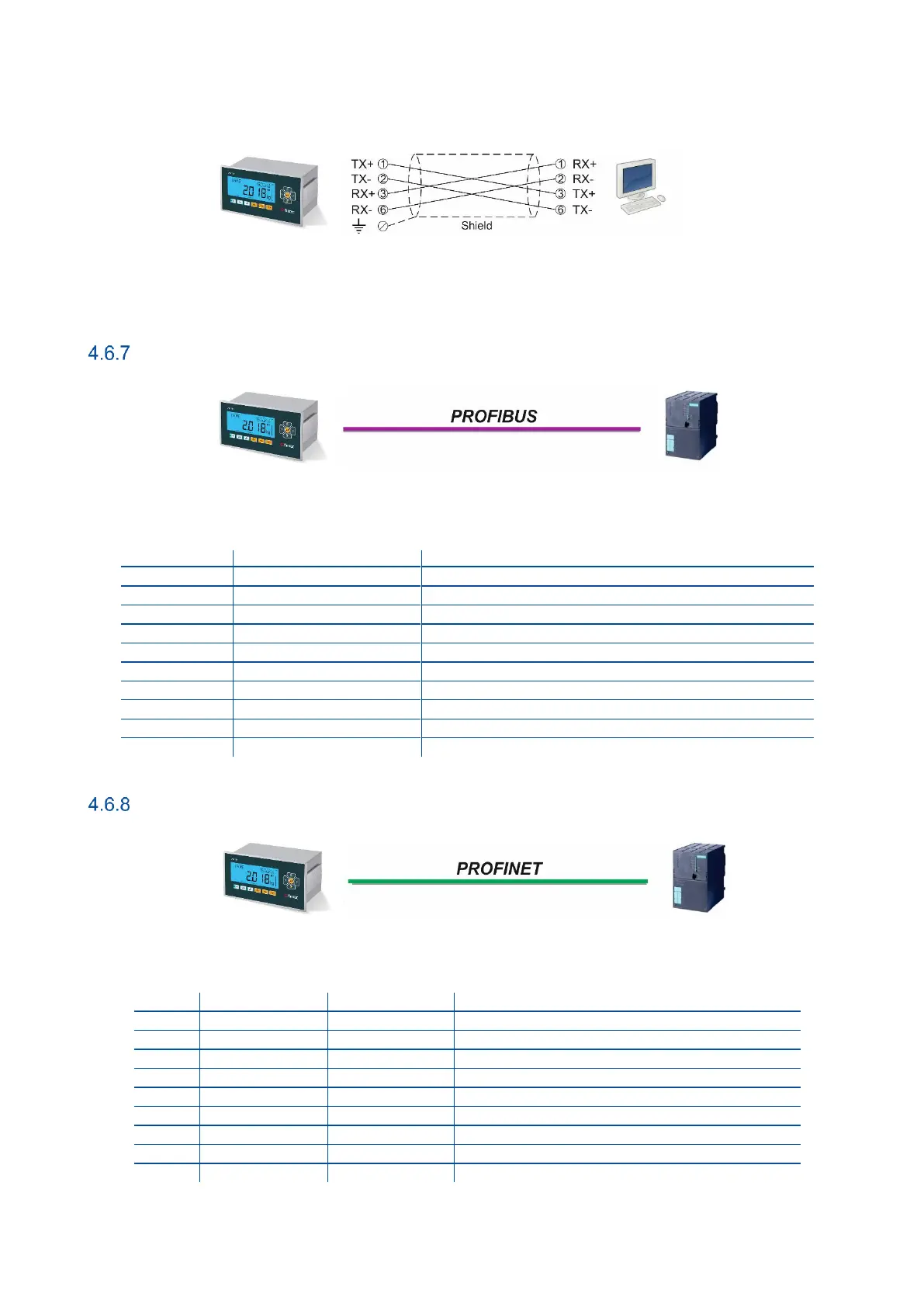
FT-111(D) Panel Weighing Indicator, Technical Manual, Rev.1.0.0, May 2019 Page 26 of 146
The PC connection cabling is done via cross cable as shown below. IP address blocks and gateway address of FT-111 and
PC should be the same in cross connection.
Figure 4.13 - PC connection with cross cable
Important note: Disconnect ndface2x set up PC software before Ethernet interfacing.
Profibus DP
Figure 4.14 - PLC Connection
PROFIBUS Connector pin configuration (DB9F)
Positive RxD / TxD, RS-485 level
+5V termination power (isolated)
Negative RxD / TxD, RS-485 level
Profinet
Figure 4.15 - PLC Connection
PROFINET Connector pin configuration (RJ45)
Differential Ethernet transmit data +
Differential Ethernet transmit data −
Differential Ethernet receive data +
Differential Ethernet receive data −