Victor Xu Page 25 12 Jan. 2011
Copyright 2011 © Shenzhen Runtianzhi Image Technology, Co., Ltd.
http://www.floradigital.com
to drive the servo system mechanism.
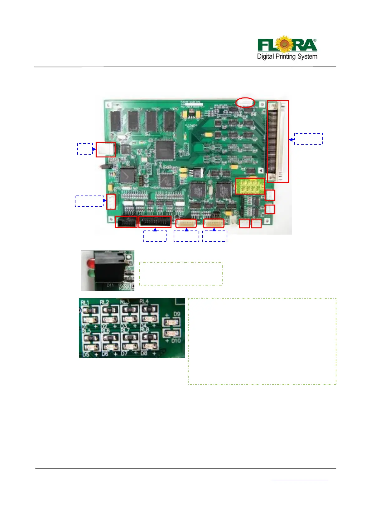
4.3.4 Servo Card
The Servo Card or sometimes Servo Driver Board serves as the movement control board
and ink control board packed into one circuit board.
Power to the corresponding ink pumps are sent by this PCB as well as the control signals
from the secondary ink tank level sensors are being received and processed. This binary
information about the status are being processed accordingly in order to provide the power to turn
on the ink pumps to fill in the secondary ink tanks.
The control for the automatic carriage height adjustment is also handled by this PCB as well
as the UV status and the carriage limit sensors. The controls for the ink prime and printhead
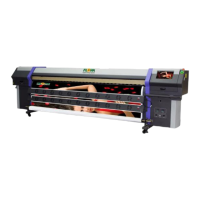
Communication indicator:
D1: NULL
D2: NULL
D3: NULL
D4: NULL
D5: Print head board indicator Communication: on
D6: Y-axis indicator Y motor moving: on
D7: Servo Card indicator Communication: on
D8: X-axis indicator Y motor moving: on
D9: RX indicator Receiving data: on
D10: TX indicator Transmitting data: on
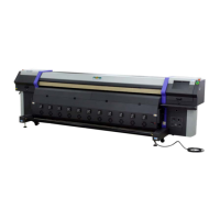
Green Led: power indicator
Red Led: connection indicator
J5
J2
J11
J10
P1
J1
J9
PC
5V in
ut
PHB JP1
SCB J5
X-axis
-axis