Victor Xu Page 44 12 Jan. 2011
Copyright 2011 © Shenzhen Runtianzhi Image Technology, Co., Ltd.
http://www.floradigital.com
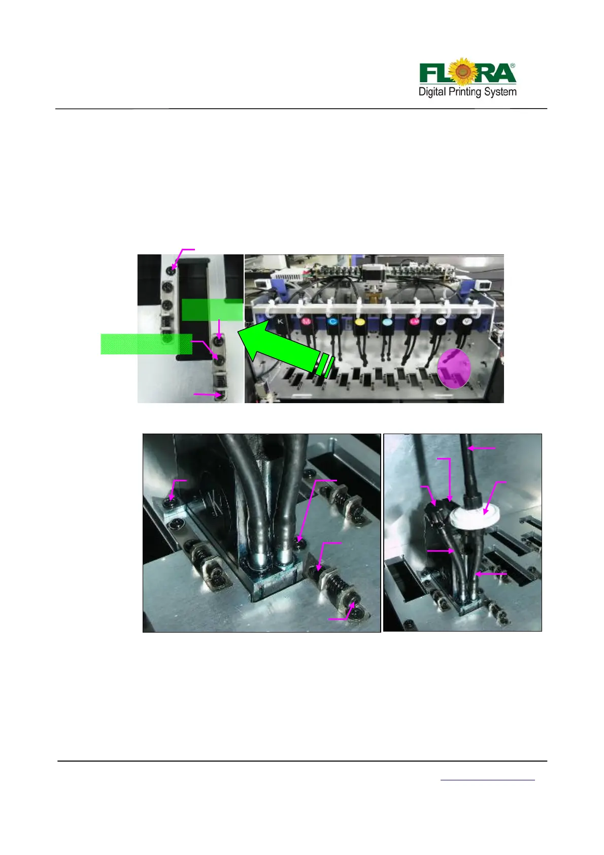
¾ Install the print head one by one by removing printhead fixation screws from the
carriage printhead mounting plate first, position the printhead and replace the two
fixation screws accordingly.
The back fixation screw must be slightly tightened to allow the printhead to move
with minimum vertical shake, while the front fixation screw must be tightened
properly before doing Y-align. Please take note of proper printhead orientation.
¾ Connect the 30pins flexible print head data cable on each print head and to the
Print head Control Board. Please take note of the proper connection of cable.
Connect the input tubing of print head to the Ink tank supply port accordingly, take
note not to interchange the connection for input and the bleeding tubes. The input
tubing should have a 20µm ink filter.
Front of Carriage with Print head
Front Printhead
fixation Screw
Mechanical
Alignment
Screw
Mechanical Alignment
mechanisms lock Screw
Back Print head
fixation Screw
Ink bleed
tubing
Print head Orientation
Mechanical
alignment screw
Back
Fixation
screw
Front
fixation
screw
Y align
mechanism
lock screw
Ink Input
tubing
Printhead
input tubing
Ink disc
20µ filter
Ink bleed
tube cap
Data Flat
cable connector
Print head Installed on Carriage