Introduction and Specification
Electrical Specifications 1
1-21
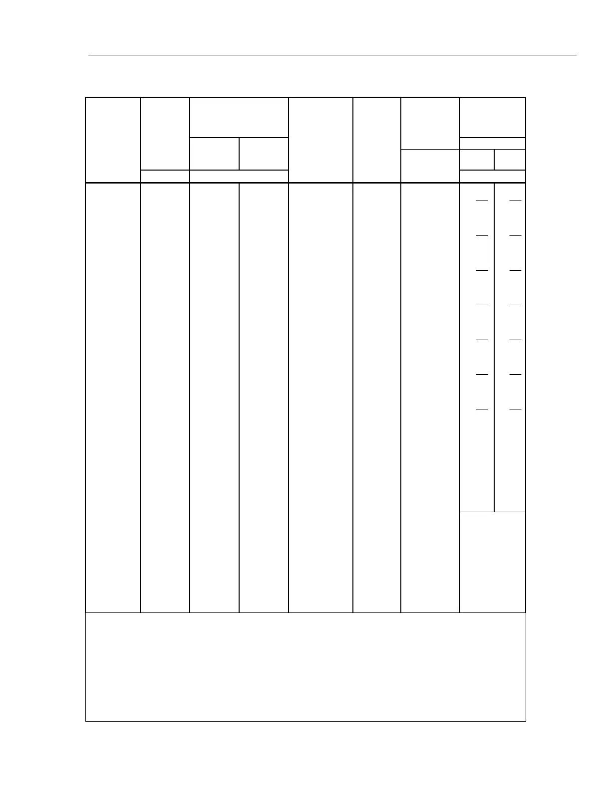
Resistance Secondary Performance Specifications and Operating Characteristics
Nominal
Value
(Ω)
Stability
±1 °C
[1]
24 Hours
Temperature Coefficient
Adder
[2]
Full Spec Load
Range
[3]
I
L
- I
U
(mA)
Maximum
Peak
Current
I
MAX
(mA)
Maximum
Difference of
Characterized
to Nominal
Value
Two-Wire
Adder Active
Compensation
[4]
10 - 40 °C
0 - 10 °C
and
40 - 50 °C
Lead Resistance
±ppm
0.1 Ω 1 Ω
±ppm ±ppm/°C ±mΩ
0
⎯ ⎯ ⎯
8 - 500 500
⎯
2 +
m
I
μV 4
4 +
m
I
μV 4
1 32 4 5 8 - 100 700 500
2 +
m
I
μV 4
4 +
m
I
μV 4
1.9 25 6 7 8 - 100 500 500
2 +
m
I
μV 4
4 +
m
I
μV 4
10 5 2 3 8 - 11 220 300
2 +
m
I
μV 4
4 +
m
I
μV 4
19 4 2 3 8 - 11 160 300
2 +
m
I
μV 4
4 +
m
I
μV 4
100 2 2 3 8 - 11 70 150
2 +
m
I
μV 4
4 +
m
I
μV 4
190 2 2 3 8 - 11 50 150
2 +
m
I
μV 4
4 +
m
I
μV 4
1 k 2 2 3 1 - 2 22 150
10 15
1.9 k 2 2 3 1 - 1.5 16 150
10 15
10 k 2 2 3
100 - 500 μA
7 150 50 60
19 k 2 2 3
50 - 250 μA
5 150
100 120
100 k 2 2 3
10 - 100 μA
1 150
I
m
= Current
produced by
Ohmmeter (A)
190 k
2 2 3
5 - 100 μA 500 μA
150
1 M
2.5 2.5 6
5 - 20 μA 100 μA
200
1.9 M
3.5 3 10
2.5 - 10 μA 50 μA
200
10 M
10 5 20
0.5 - 2 μA 10 μA
300
19 M
20 8 40
0.25 - 1 μA 5 μA
300
100 M
50 12 100 50 - 200 nA
1 μA
500
Notes:
1. Stability specifications are included in the Absolute specification values in the primary specification tables.
2. Temperature coefficient is an adder to Absolute specifications that does not apply unless operated more than 5 °C from calibration
temperature, or calibrated outside the range 19 °C to 24 °C. Two examples:
- Calibrate at 20 °C: Temperature coefficient adder is not required unless operated below 15 °C or above 25 °C.
- Calibrate at 26 °C: Add 2 °C temperature coefficient adder. Additional temperature coefficient adder is not required unless
operated below 21 °C or above 31 °C.
3. Refer to current derating factors table for loads outside of this range.
4. Active two-wire compensation may be selected for values less than 100 kΩ, with either the front panel or the meter input terminals
as reference plane. Active compensation is limited to 11 mA load, and to 2 V burden. Two-wire compensation can be used only
with Ω-meters that source continuous (not pulsed) dc current.