Features
Rear-Panel Features 3
3-5
Rear-Panel Features
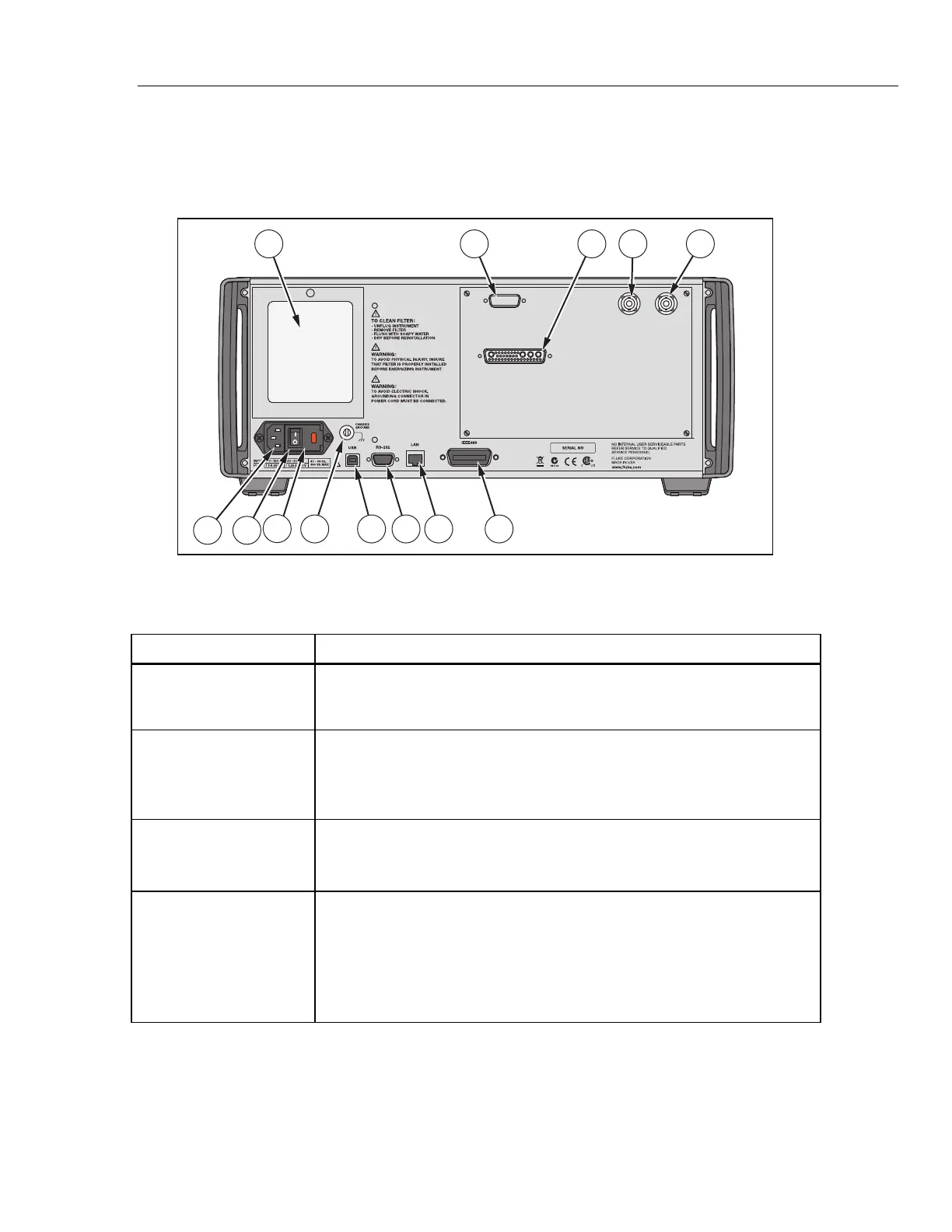
Rear-panel features (including all terminals, sockets, and connectors) are shown in
Figure 3-2. Each rear-panel feature is briefly described in Table 3-2.
1
1311109
3 52
768
12
4
hhp009.eps
Figure 3-2. Rear-Panel Features
Table 3-2. Rear-Panel Features
Item Description
Fan Filter
The filter covers the air intake to keep dust and debris out of chassis. Fans
inside the Calibrator provide a constant cooling air flow throughout the
chassis. Circuitry inside the Calibrator monitors correct operation of the
internal fans.
52120A
Transconductance
Amplifier Connector
Provides the analog and digital interface for the Fluke 52120A
Transconductance Amplifier. After the 52120A is connected to the 52120A
AMPLIFIER connector, control the 52120A from the Calibrator front panel
or by remote commands. Refer to "Auxiliary Amplifier Use" in Chapter 4 for
details.
5725A Amplifier
Connector
Provides the analog and digital interface for the Fluke 5725A Amplifier.
After the 5725A is connected to the 5725A AMPLIFIER connector, control
the 5725A from the Calibrator front panel or by remote commands. Refer to
"Auxiliary Amplifier Use" in Chapter 4 for details.
VARIABLE PHASE
OUT BNC Connector
Provides access to a variable-phase nominal 2.5 V rms sine-wave signal,
intended for a 3 kΩ load. The phase of this signal can be adjusted with the
arrow keys and rotary knob (or by remote commands) to lead or lag the
main Calibrator output signal by up to 180 degrees. The connector shell is
not connected directly to chassis ground. It is connected internally to the
OUTPUT LO binding post. The maximum allowable potential between the
connector shell and chassis ground is 20 V peak. Refer to "Variable Phase
Output" in Chapter 4 for details.