5730A
Operators Manual
1-30
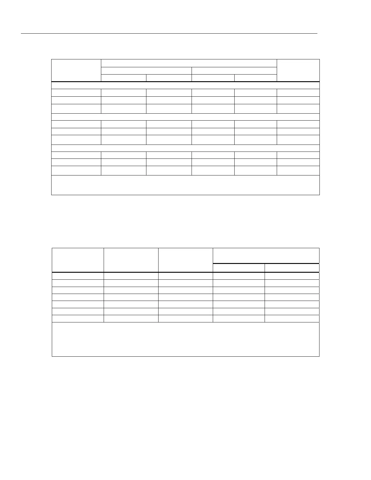
Maximum Distortion and Noise
Frequency
Distortion
[1]
Noise
16 Hz to 10 MHz
LCOMP OFF LCOMP ON
dBc Current dBc Current
2 Amp Range
16 Hz to 850 Hz
-76
42 μA
-70
83 μA
-60 dB
850 Hz to 6 kHz
-52
662 μA
-46 1.3 mA -60 dB
6 kHz to 10 kHz
[2]
-40 2.6 mA -35 4.7 mA -60 dB
20 Amp Range
16 Hz to 850 Hz
-76
418 μA
-60 2.6 mA -70 dB
850 Hz to 6 kHz -52 6.6 mA -42 20.9 mA -70 dB
6 kHz to 10 kHz
[2]
-40 26.4 mA -35 46.9 mA -70 dB
120 Amp Range
16 Hz to 850 Hz -76 2.5 mA -60 15.8 mA -70 dB
850 Hz to 6 kHz -52 39.7 mA -42 125.7 mA -70 dB
6 kHz to 10 kHz
[2]
-40 158.2 ma -35 281.3 mA -70 dB
Notes:
1. Use dB or Current. Whichever is larger.
2. Interharmonics only above 6 kHz.
52120A/COIL 3 kA 25-Turn Coil
Number of Turns ................................................... 25
Minimum internal jaw dimension to clear wires 26 mm (width) x 36 mm (length)
Maximum Input Current ........................................ 120 A continuous with built-in 12 V fan on
Maximum Voltage ................................................. 4.5 V rms
Specification
Input Current
[1]
Frequency
Effective Current
Amp-turns
52120A + Coil Specification
[2]
±(% of Amp-turns + % of 52120A range)
% of Amp-turns % of 52120A Range
0 A to 100 A DC 0 to 2500 0.7 % 0.7 %
0 A to 120 A 10 Hz to 65 Hz 0 to 3000 0.7 % 0.7 %
0 A to 120 A 65 Hz to 300 Hz 0 to 3000 0.7 % 0.7 %
0 A to 40 A 300 Hz to 1 kHz 0 to 1000 0.7 % 0.7 %
0 A to 12 A 1 kHz to 3 kHz 0 to 300 0.8 % 1.0 %
0 A to 3 A 3 kHz to 6 kHz 0 to 75 1.5 % 1.0 %
0 A to 1 A 6 kHz to 10 kHz 0 to 25 5.0 % 1.0 %
Notes:
1. The inductance and mutual inductance of the 25 turn coil and clamp that is measured causes a frequency dependent compliance
voltage across the coil. The length and configuration of the cables that connect the current to the coil also have an effect.
Maximum input current is 120 A input at approximately 100 Hz. Maximum current input decreases to approximately 0.8 A at
10 kHz.
2. Includes coil/clamp interaction.