Introduction and Specification
Electrical Specifications 1
1-31
52120A/COIL 6 kA 50-Turn Coil
Number of Turns ................................................... 50
Minimum Flexible Probe Length .......................... 500 mm
Maximum Input Current ........................................ 120 A continuous with built-in 12 V fan on
Maximum Voltage ................................................. 4.5 V rms
Specification
Input Current
[1]
Frequency
Effective Current
Amp-turns
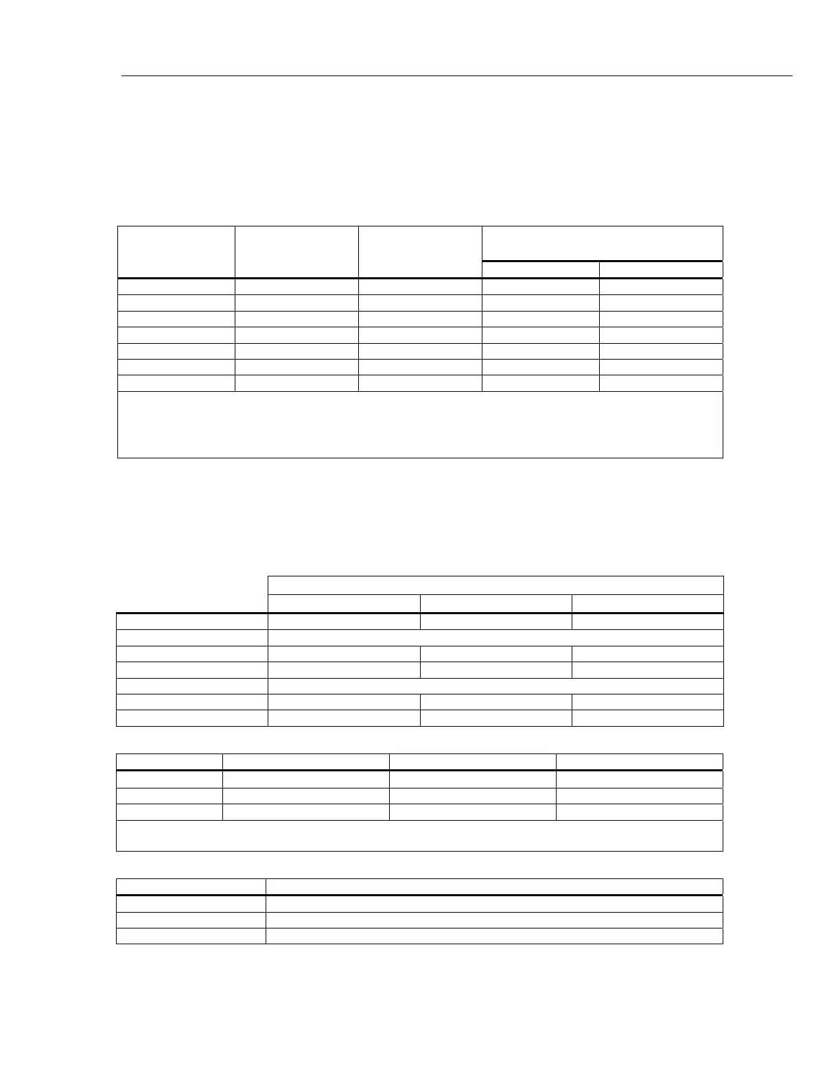
52120A + Coil Specification
[2]
±(% of Amp-turns + % of 52120A range)
% of Amp-turns % of 52120A Range
0 A to 100 A DC 0 to 5000 0.7 % 0.7 %
0 A to 120 A 10 Hz to 65 Hz 0 to 6000 0.7 % 0.7 %
0 A to 120 A 65 Hz to 300 Hz 0 to 6000 0.7 % 0.7 %
0 A to 120 A 300 Hz to 1 kHz 0 to 6000 0.7 % 0.7 %
0 A to 120 A 1 kHz to 3 kHz 0 to 6000 0.8 % 1.0 %
0 A to 25 A 3 kHz to 6 kHz 0 to 1250 1.5 % 1.0 %
0 A to 13 A 6 kHz to 10 kHz 0 to 650 5.0 % 1.0 %
Notes:
1. The inductance and mutual inductance of the 50 turn coil causes a frequency dependent compliance voltage across the coil.
Maximum frequency for 120 A input current is approximately 600 Hz. Maximum current input decreases to approximately 13 A at
10 kHz.
2. Includes coil/probe interaction.
Note
The specifications for these coils are at 99 % confidence level and are the combined
specification of the coil and a 52120A. If the coils are used with other current
sources the calibration specification of the coils alone is 0.65 % (99 % confidence
level) from 0 Hz to 10 kHz.
Operating Limits
Output Current Range
2 A 20 A 120 A
Current Output (Max.) 2 A rms 20 A rms 120 A rms
Current Input
Input Current (Max.) 200 mA rms 200 mA rms 120 mA rms
Current gain 10 100 1,000
Voltage Input
Input Voltage (Max.) 2 V rms 2 V rms 1.2 V rms
Transconductance 1 Siemen 10 Siemens 100 Siemens
120 A Range Current/Frequency Limits
Frequency Maximum Output Current Maximum Current Input Maximum Voltage Input
DC
±100 A ±100 mA ±1.0 V
<10 Hz 100 A pk (70 A rms) 100 mA pk (70 mA rms) 1.0 V pk (0.7 V rms)
10 Hz to 10 kHz 170 A pk (120 A rms) 170 mA pk (120 mA rms) 1.7 V pk (1.2 V rms)
Note:
The 2 A and 20 A ranges operate at full output current from DC to 10 kHz.
Output Isolation
Frequency Maximum Voltage Signal Applied to any Output Current Terminal with respect to Earth
DC to 850 Hz 600 V rms, 850 V pk, limited 2 A rms, no transient overvoltages
850 Hz to 3 kHz 100 V rms, 142 V pk, limited 2 A rms, no transient overvoltages
3 kHz to 10 kHz 33 V rms, 47 V pk, limited 2 A rms, no transient overvoltages