830
Users Manual
104
4. Readjust the beam into the target square using the yellow prism knob and the
metal thumbwheel.
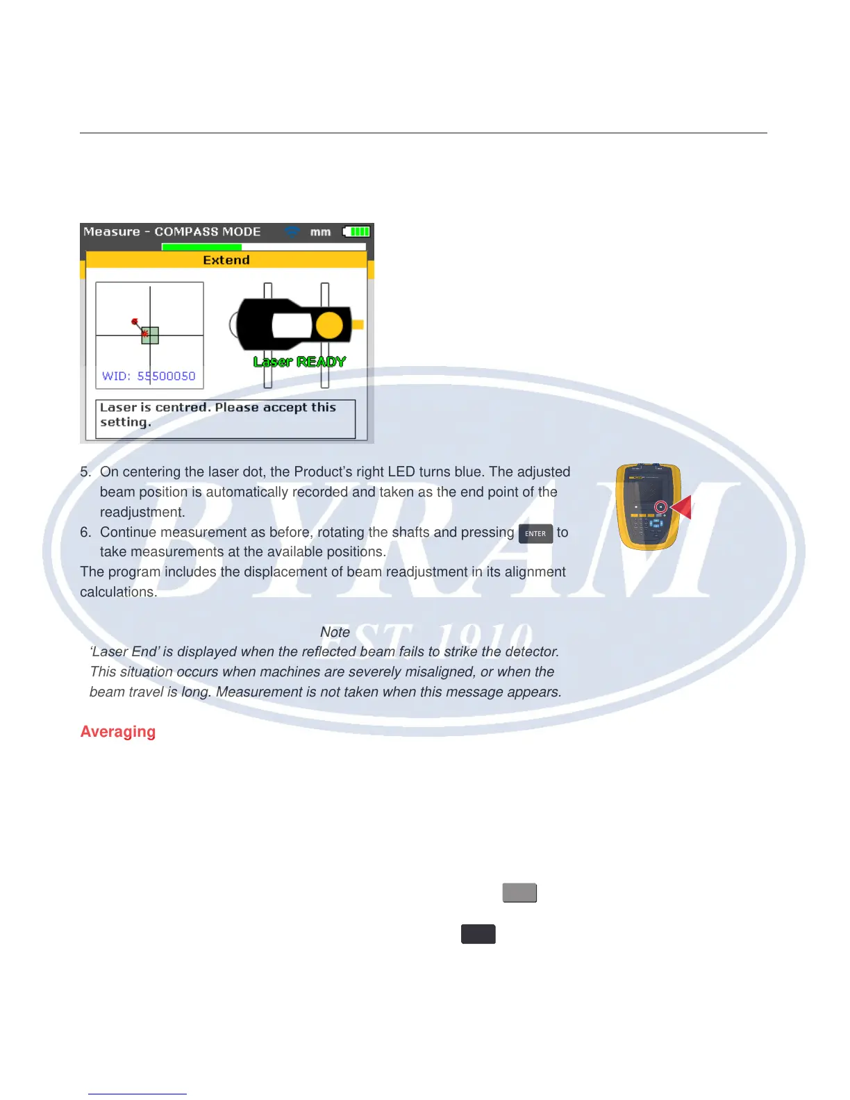
5. On centering the laser dot, the Product’s right LED turns blue. The adjusted
beam position is automatically recorded and taken as the end point of the
readjustment.
6. Continue measurement as before, rotating the shafts and pressing
ENTER
to
take measurements at the available positions.
The program includes the displacement of beam readjustment in its alignment
calculations.
Note
‘Laser End’ is displayed when the reected beam fails to strike the detector.
This situation occurs when machines are severely misaligned, or when the
beam travel is long. Measurement is not taken when this message appears.
Averaging
In certain industrial conditions, it may be necessary to increase the number
of measurements to be averaged when taking readings to attain the desired
accuracy. Particular cases include applications with increased machinery
vibration. An increased averaging also improves the accuracy when measuring
sleeve bearings, white metal bearings and journal bearings.
The number of individual readings which are averaged together to form one
measurement are set via the “Measurement options” screen. Press
MENU
to
access the menu. While in the menu screen use the navigation keys to highlight
the ‘Measure options’ icon and conrm selection by pressing
ENTER
. The
“Measurement options” screen opens.
830
LASER ALIGNMENT TOOL
SETUP MEASURE
DIAGNOSE MENU
CLEARENTER
BACK
1
2
ABC
3
DEF
4
GHI
5
JKL
6
MNO
7
PQRS
8
TUV
9
WXYZ
+
-
0
space
.
/
.