i
Table of Contents
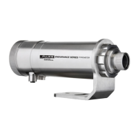
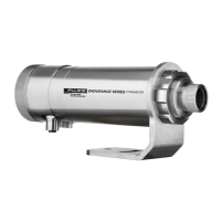
Title Page
1. Safety Instructions .................................................................................. 1
2. Description ............................................................................................... 3
2.1. Theory of Operation for Ratio (2-Color) Sensors ......................................... 5
2.1.1. Partially Obscured Targets ..................................................................... 5
2.1.2. Targets Smaller Than Field of View ........................................................ 5
2.1.3. Emissivity and 1-Color (single wavelength) measurements .................... 5
2.1.4. Slope (2-Color ratio) measurements ....................................................... 6
3. Technical Data ......................................................................................... 7
3.1. General Specifications ................................................................................ 7
3.2. Electrical Specifications .............................................................................. 8
3.3. Measurement Specifications ....................................................................... 11
3.4. Optical Specifications .................................................................................. 12
3.4.1. Measurement spot size regarding the selected focus and model options 13
3.5. Dimensions ................................................................................................. 14
3.6. Scope of Delivery ........................................................................................ 15
4. Sensor Location....................................................................................... 15
4.1. Ambient Temperature ................................................................................. 15
4.2. Atmospheric Quality .................................................................................... 15
4.3. Electrical Interference ................................................................................. 16
4.4. Distance to Object ...................................................................................... 16
4.5. Sensor Placement (1-Color Mode) .............................................................. 16
4.6. Sensor Placement (2-Color Mode) .............................................................. 17
4.7. Viewing Angles ........................................................................................... 18
5. Installation................................................................................................ 18
5.1. Mounting the Sensor ................................................................................... 18
5.2. Aiming and Focusing .................................................................................. 18
5.3. Electrical Installation ................................................................................... 20
5.3.1. M16 12-Pin DIN Connector Signal Assignment ...................................... 20
5.3.2. M12 4-Socket LAN/Ethernet Connector.................................................. 20
5.3.3. Accessory Cables and Terminal Block ................................................... 21
5.3.4. Power Supply ......................................................................................... 23
5.3.5. Computer Interfacing via RS485 link ...................................................... 23
5.3.6. Addressing the Endurance sensor in a RS485 Multidrop Network .......... 24
6. Device Control ......................................................................................... 25
6.1. Control Panel .............................................................................................. 25
6.1.1. The Object / Target Temperature Display (green 7-segment LED type) . 25
6.1.2. The Screen / Menu Display .................................................................... 26
6.1.3. The LASER / LED / CAMERA Indicator LED (red) ................................. 26
6.1.4. The Status Indicator LED (green) ........................................................... 26
6.1.5. The 4 Control Panel Pushbuttons ........................................................... 26
6.2. The control panel menu structure and their associated entries ................... 27
6.2.1. The INFORMATION MENU .................................................................... 29
6.2.2. The CONFIGURATION MENU ............................................................... 31
6.2.3. The UNIT SETUP MENU ....................................................................... 33
6.2.4. The INTERFACE MENU ........................................................................ 36
6.2.5. The ANALOG MENU .............................................................................. 38