TFC100 Rev180215
4
List of Figures
Figure 1. General System Layout ...................................................................................................................................11
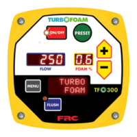
Figure 2. Controls and Indicators ....................................................................................................................................14
Figure L1. TFC Control Module Mounting Dimensions ................................................................................................41
Figure L2. Foam Pump Assembly Mounting Dimensions..............................................................................................43
Figure L3. Foam Pump Assembly Dimensions ..............................................................................................................44
Figure L4. Manual ABF Selector Mounting Dimensions ...............................................................................................45
Figure L5. Electric ABF Selector Mounting Dimensions ...............................................................................................46
Figure L6. TFC100/200 Plumbing Single Tank System .................................................................................................49
Figure L7. TFC100/200/300 Plumbing Single Tank System w/Electric Flush Valve ....................................................50
Figure L8. TFC200 Plumbing Two Tank System w/Manual ABF Selector ...................................................................51
Figure L9. TFC400 Plumbing Two Tank System w/Electric ABF Selector ...................................................................52
Figure L10. Discharge Check Valve Assembly Dimensions ..........................................................................................53
Figure L11. Flow Sensor Location Guidelines ...............................................................................................................54
Figure L12. Saddle Clamp Installation ...........................................................................................................................55
Figure L13. Weldment Installation .................................................................................................................................56
Figure L14. Summing Box Mounting Dimensions.........................................................................................................57
Figure W1. System Cables ..............................................................................................................................................59
Figure W2. Control Module Wiring ................................................................................................................................61
Figure W3. Foam Pump Control Wiring .........................................................................................................................62
Figure W4. Electric Flush Valve Wiring ........................................................................................................................63
Figure W5. Manual ABF Selector Wiring .....................................................................................................................63
Figure W6. Electric ABF Selector Wiring .....................................................................................................................64
Figure W7. Flow Sensor Wiring ....................................................................................................................................65
Figure W8. Summing Box Wiring .................................................................................................................................65
Figure W9. Remote Switch Wiring ................................................................................................................................66
Figure W10. Optional Remote Control Module Wiring ................................................................................................67
Figure P1. TurboFoam Control Modules ........................................................................................................................69
Figure P2. TurboFoam Single Tank System Cables .......................................................................................................71
Figure P3. TurboFoam Two Tank System Cables ...........................................................................................................73
Figure P4. 1.6, 2.1 and 2.6 GPM Foam Pump Assembly ...............................................................................................75
Figure P5. 3.5, 5.0, 6.2, and 6.5 GPM Foam Pump Assembly .......................................................................................77
Figure P6. Electric ABF Selector and Electric Flush Valve ............................................................................................79
Figure P7. Manual ABF Selector ....................................................................................................................................81
Figure P8. Miscellaneous Plumbing Components ..........................................................................................................83
List of Tables
Table 1. TurboFoam Standard Components and Options .................................................................................................6
Table 2. Foam Pump Assembly Dimensions ....................................................................................................................7
Table 3. Direct Injection Foam Proportioning System Specications ..............................................................................8
Table 4. Detailed Information .........................................................................................................................................16
Table 5. Error Codes .......................................................................................................................................................19
Table 6. Fault Warning Codes .........................................................................................................................................20
Table 7. Program Functions P100 Codes Quick Reference ............................................................................................24
Table 8. Calibration Failure Messages ............................................................................................................................30
Table 9. Error Codes and Fault Warnings Troubleshooting ............................................................................................39
Table 10. Foam Pump DC Supply Power Input Wire Size .............................................................................................62
 Loading...